Vehicle control system

a technology of vehicle control and control system, which is applied in the direction of gearing control, gearing element, belt/chain/gearring, etc., can solve the problems of not being able to detect an actual shift range and being unable to make the switch to the instructed shift rang

Inactive Publication Date: 2007-04-19
DENSO CORP +1
View PDF3 Cites 21 Cited by
  • Summary
  • Abstract
  • Description
  • Claims
  • Application Information

AI Technical Summary

Benefits of technology

[0006] According to the present invention, when a trouble of the range detector is detected, a shift-changing valve is moved until the movement is restricted by a restriction member, whereby the position of one end in a reciprocative movement range of the shift-changing valve can be defined. In the present invention, the amount of operation of an actuator performed when moving the shift-changing valve from a position corresponding to a certain shift range to a position corresponding to another shift range is stored in a memory for each shift range interval. Therefore, when it is possible to define the position of one end in the reciprocative movement range, the shift-changing valve can be moved to the position corresponding to an instructed shift range by operating the actuator until the amount of operation thereof becomes coincident with that stored in the memory on the basis of the established position. Thus, even upon occurrence of a trouble in the range detector, it is possible to make switching to a shift range instructed by a shift range changing command.

Problems solved by technology

According to such a system, however, upon occurrence of a trouble of the range detector such as, for example, failure of the range detector itself, disconnection of a harness for connection between the range detector and a controller in the shift-by-wire system, or a short-circuit of the harness, it becomes no longer possible to detect an actual shift range and hence impossible to make switching to the instructed shift range.

Method used


Image

  • Vehicle control system
  • Vehicle control system
  • Vehicle control system

Examples


first embodiment

(First Embodiment)

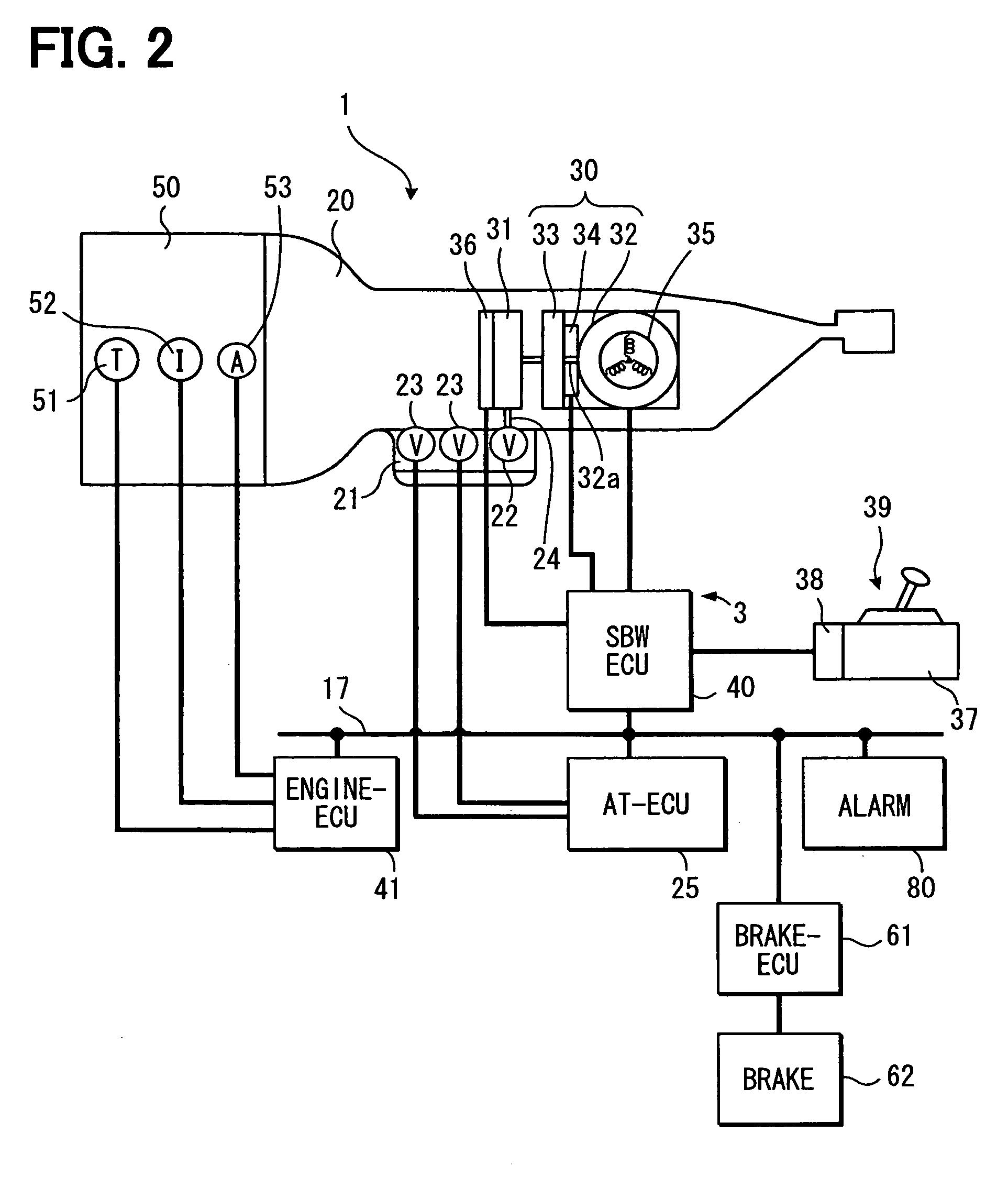
[0018]FIG. 2 is a schematic diagram showing a vehicle system 1 using a vehicle control system according to a first embodiment of the present invention. A shift-by-wire system 3 as the vehicle control system is a system for controlling the travel of a vehicle and it is connected electrically or optically through an interior LAN line 17 to an automatic transmission controlling ECU (hereinafter referred to as “AT controlling ECU”) 25, an engine controlling ECU 41, a brake controlling ECU 61, and an alarm device 80. A detent plate 72 (see FIG. 3) as a rotating member is engaged with a shift range switching valve 24 (see FIG. 3) of an automatic transmission 20, whereby the shift-by-wire system 3 is connected mechanically to the automatic transmission 20. To the shift-by-wire system 3 is connected a shift range selector 39 which outputs a shift range changing command to the shift-by-wire system 3, the shift range changing command instructing a change to an instructed shi...


PUM


Abstract

A controller determines the state of the range detector on the basis of the detection signals detected by the range detector, then when the range detector is determined to be in an abnormal condition, the controller moves the shift-changing valve until the movement is inhibited by the restriction member, thereby establishes the position of one end, and controls the actuator with respect to the established one end position and on the basis of the amount of operation to move the shift-changing valve to the position corresponding to an instructed shift range. Even when the range detector is in an abnormal condition, it is possible to make a change to the shift range corresponding to a shift range changing command.

Description

CROSS-REFERENCE TO RELATED APPLICATION [0001] This application is based on Japanese Patent Application No. 2005-188282 filed on Jun. 28, 2005, the disclosure of which is incorporated herein by reference. FIELD OF THE INVENTION [0002] The present invention relates to a vehicle control system provided with a shift-by-wire system. BACKGROUND OF THE INVENTION [0003] JP-2000-170905A (USP-6,230,576) shows a shift-by-wire system of an auto-transmission. In this system, a shift range selected by a vehicle occupant is detected, and a shift-changing valve for changing the shift range in an automatic transmission is actuated by an actuator such as an electric motor in accordance with the detected shift range. [0004] The shift-by-wire system is provided with a range detector. When a change of the shift range is instructed, an electric current is supplied to an electric motor until an actual shift range detected by the shift range detector becomes coincident with the instructed shift range. Acco...

Claims


Application Information

Patent Timeline
Patent Type & Authority Applications(United States)
IPC IPC(8): B60W10/04B60T7/12F16H61/28
CPCF16H61/12F16H61/32F16H2061/1224Y10T74/19251F16H2061/326Y10T477/675F16H2061/1288
Inventor MATSUZAKI, HARUKIKASHIWAGI, TOMOYUKISHINOJIMA, MASAAKIHORI, MASASHI
Owner DENSO CORP
Why Eureka
Try Eureka