Molded ferrule with reference surface for end face geometry measurement

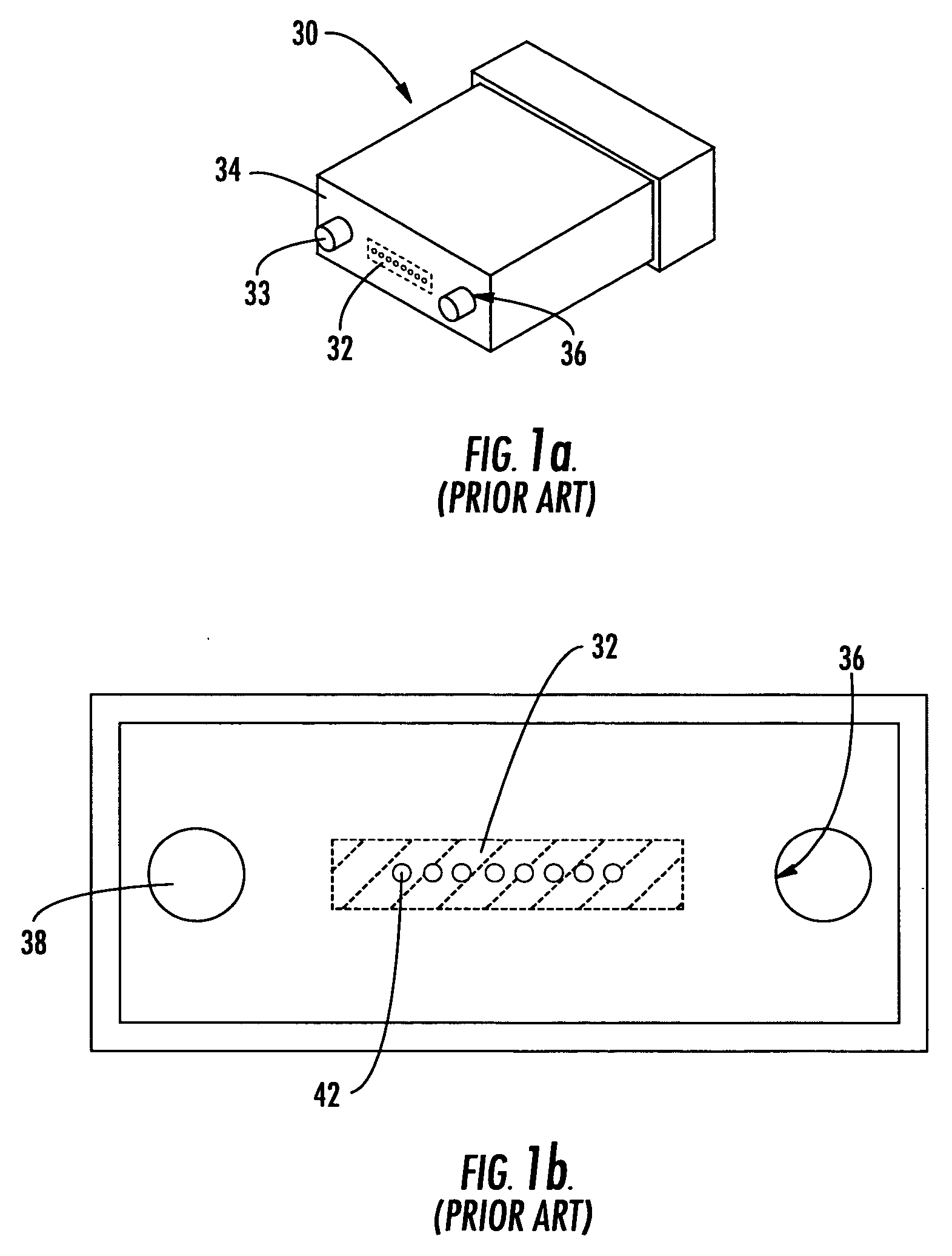
a ferrule and geometry technology, applied in the field of multifiber connectors, can solve the problems of extremely small size, easy loss of measurement pins b>33/b>, and high manufacturing cost of measurement pins

Inactive Publication Date: 2007-05-03
CORNING OPTICAL COMM LLC
View PDF16 Cites 32 Cited by
  • Summary
  • Abstract
  • Description
  • Claims
  • Application Information

AI Technical Summary

Benefits of technology

[0010] To achieve the foregoing and other objects, the present invention, as embodied and broadly described herein, provides various embodiments of multifiber ferrules comprising a molded ferrule body having an end face and defining a plurality of bores extending through the ferrule body for receiving end portions of respective optical fibers, the ferrule body further defining at least one opening through the end face adapted to receive an alignment member for aligning the end portions of the respective optical fibers with corresponding end portions of optical fibers of a mating multifiber ferrule, and at least

Problems solved by technology

For one, the measurement pins 33 are very expensive to manufacture because of the very precise machining of one of their ends.
Furthermore, the measurement pins 33 may be easily lost due to their extremely small size.
Also, when using the ends of the measurement pins 33 as a reference surface, it is necessary to make the optical measurements using a relatively expensive inte

Method used


Image

  • Molded ferrule with reference surface for end face geometry measurement
  • Molded ferrule with reference surface for end face geometry measurement
  • Molded ferrule with reference surface for end face geometry measurement

Examples


Embodiment Construction

[0036] The present invention will now be described more fully hereinafter with reference to the accompanying drawings in which preferred embodiments of the invention are shown. This invention may, however, be embodied in many different forms and should not be construed as limited to the embodiments set forth herein. These exemplary embodiments are provided so that this disclosure will be both thorough and complete, and will fully convey the scope of the invention to those skilled in the art. Like reference numbers refer to like elements throughout the various drawings.

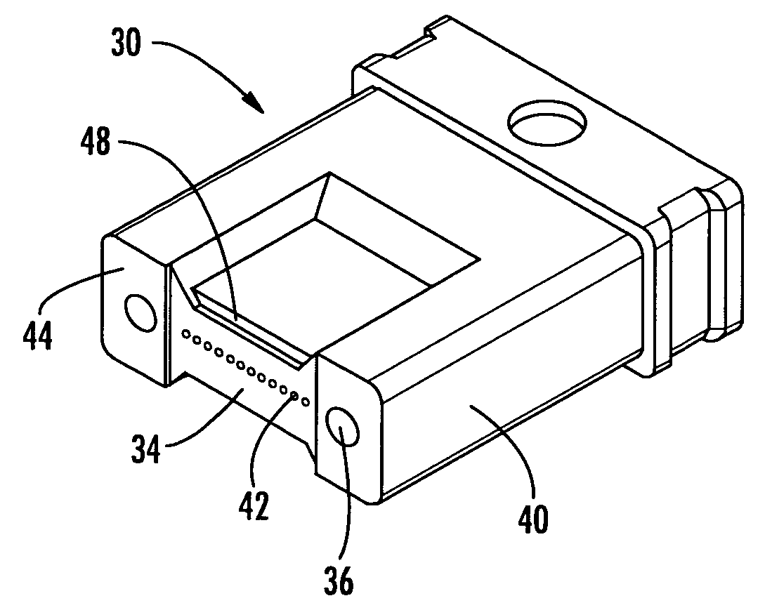
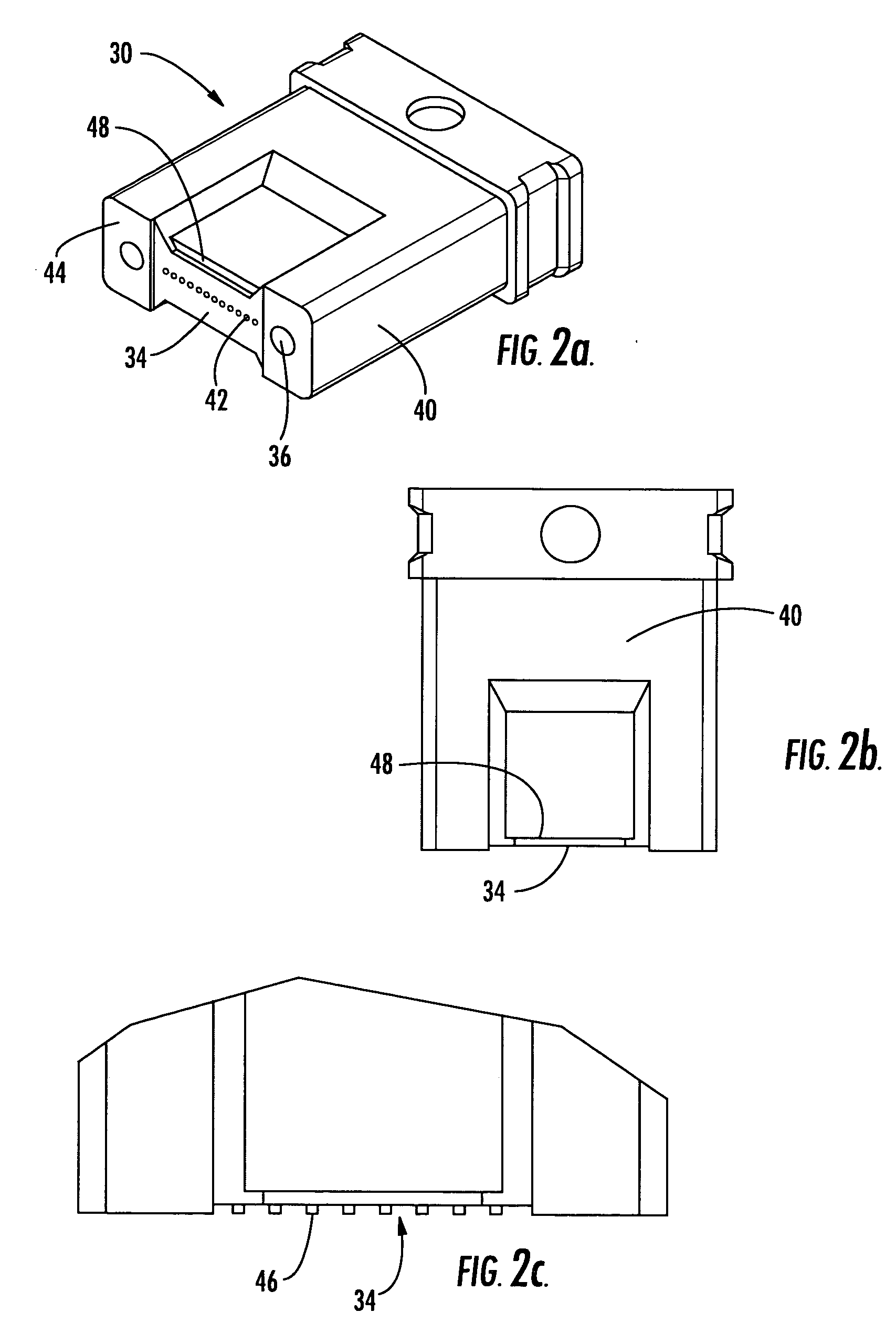
[0037] The present invention describes molded fiber optic ferrules and methods for making the same. In various embodiments, the molding process produces a fiber optic ferrule having an integrally formed geometry feature that functions as a reference surface for allowing accurate end face geometry measurement. In specific embodiments, the molding process produces a ferrule having at least one geometric reference featur...


PUM


Abstract

A ferrule comprising a molded ferrule body defining fiber bores, an end face of a connective end of the ferrule positioned about the fiber bores, and an integral reference surface for determining the angularity of the end face. The integral reference surface is not machined subsequent to a ferrule molding process and is accessible after assembly of the ferrule body into a connector body. A multi-fiber ferrule comprising a connective end defining an end face, a rear non-connective portion defining a protruding shoulder, and an integral reference datum positioned on a surface of the shoulder accessible for determining the angularity of a plane defined by the end face, wherein the integral datum is accessible when the ferrule is received within a connector body.

Description

CROSS-REFERENCE TO RELATED APPLICATIONS [0001] This application is a Continuation-In-Part of pending U.S. patent application Ser. No. 10 / 652,119 filed Aug. 29, 2003 and entitled “Molded Fiber Optic Ferrule with Integrally Formed Geometry Features”, the contents of which are hereby incorporated by reference.BACKGROUND OF THE INVENTION [0002] 1. Field of the Invention [0003] The present invention relates generally to the field of multifiber connectors and, more specifically, to molded fiber optic ferrules with an integral reference surface for end face geometry measurement. [0004] 2. Description of the Related Art [0005] Optical fibers are used for a variety of applications including voice communications, data transmission and the like. In order to interconnect a plurality of optical fibers with a minimum amount of attenuation, a pair of multifiber connectors is preferably mated such that the opposing optical fibers are biased into contact with one another. To achieve optimal transmis...

Claims


Application Information

Patent Timeline
IPC IPC(8): G02B6/38
CPCG02B6/3839G02B6/3863G02B6/3865G02B6/3885
Inventor DEAN, DAVID L. JR.ELKINS, ROBERT B. IILUTHER, JAMES P.
Owner CORNING OPTICAL COMM LLC
Why Eureka
Try Eureka