

Coolant and cooling system
a cooling system and cooling technology, applied in the field of cooling system, can solve the problems of increasing conductivity, affecting the safety standard of the high voltage safety of electric vehicles (500 /v), so as to prevent the degradation of the quality of the coolant, reduce the effect of rust and corrosion resistance, and reduce the effect of heat loss
Inactive Publication Date: 2007-05-10
TOYOTA JIDOSHA KK
View PDF19 Cites 12 Cited by
- Summary
- Abstract
- Description
- Claims
- Application Information
AI Technical Summary
Benefits of technology
[0015] Secondly, the present invention relates to a cooling system for a fuel cell, comprising a cooling circuit in which the above coolant and inert gas are included. The cooling system provides low conductivity, anti-rust properties, high heat transfer properties and anti-freezing properties. In addition, the system is capable of preventing degradat
Problems solved by technology
As described above, the coolants currently used are aqueous, and so the high voltage safety standard for electric vehicles (500 Ω/V) cannot be met.
Moreover, washing of the inside of cooling components before assembling to prevent increase in the conductivity caused by substances eluted from the components at initial stages involves high costs.
Further, since most add
Method used
View moreImage
Smart ImageViewing Examples

Examples
 PUM
 Abstract
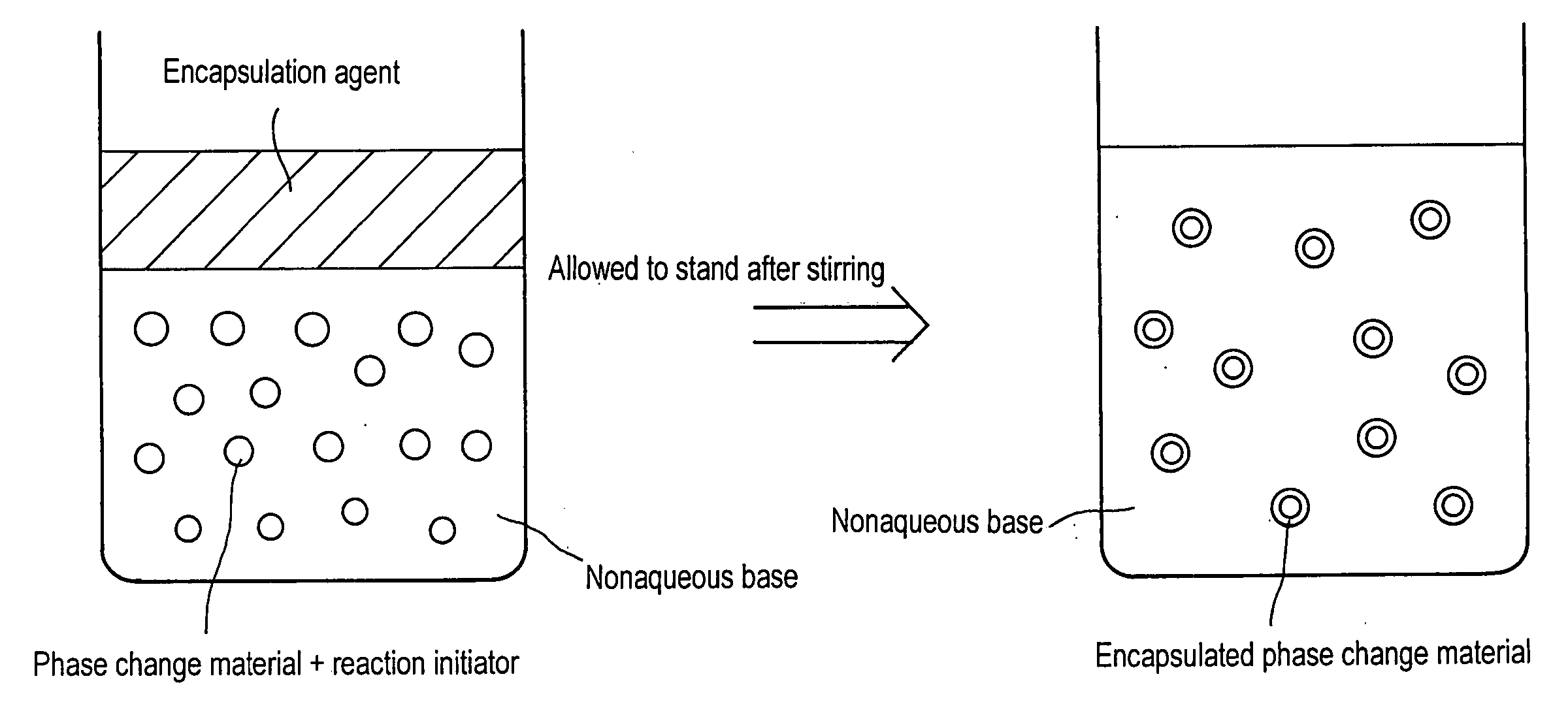
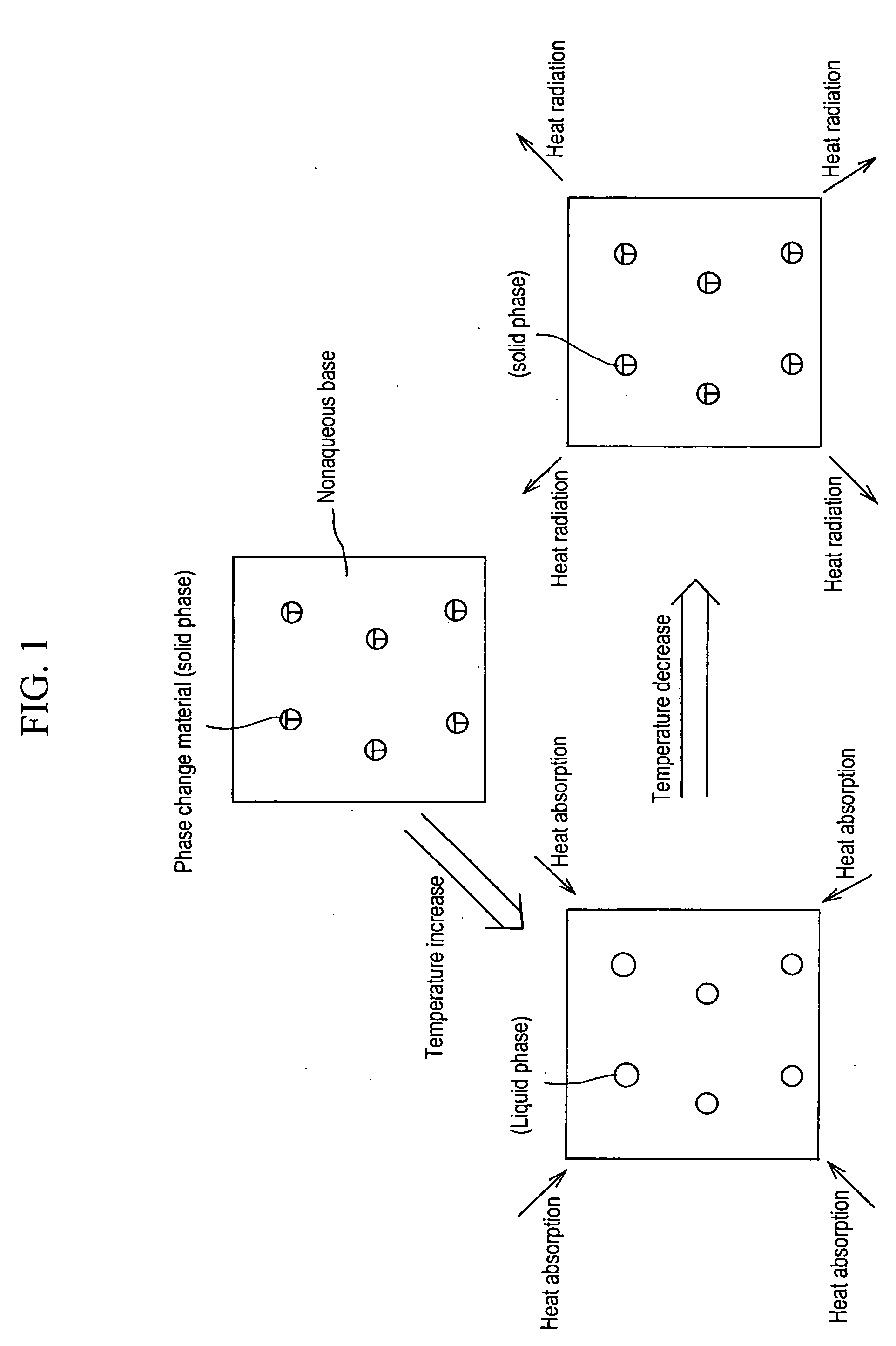
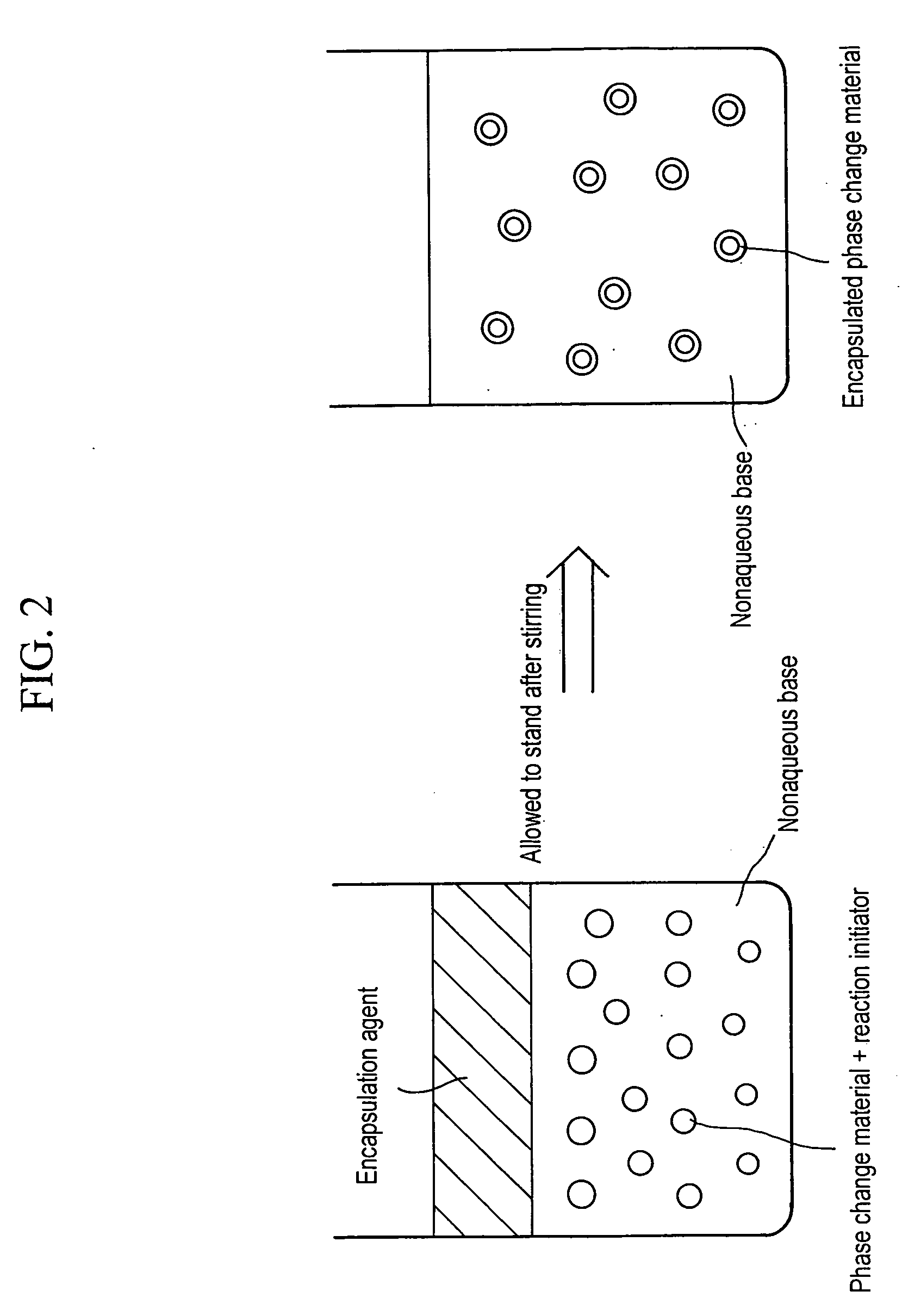
A coolant comprising a nonaqueous base. A phase change material may be dispersed or a highly heat conductive material may be dispersed or dissolved in the nonaqueous base. A nonaqueous coolant for a fuel cell excellent in heat transfer characteristics is provided as a coolant for fuel cell stacks.
Description
TECHNICAL FIELD [0001] The present invention relates to a coolant and a cooling system using the coolant. More specifically, the present invention relates to a coolant for a fuel cell, in particular, a coolant for a fuel cell for vehicles, and a cooling system for a fuel cell. BACKGROUND ART [0002] Generally, a stack of a fuel cell has a stacked structure of a plurality of cells, in which a cooling plate for cooling the stack (cells) is inserted between each sub-stack composed of a few layers of cells. The cooling plate has a coolant channel inside, through which a coolant flows so as to cool the stack. As herein described, since a coolant for a fuel cell circulates through a stack where electric power is generated, namely, between sub-stacks, high insulation performance is required in order to prevent electric leak to the outside of the stack and lowering of electrical efficiency caused by the resistance in the coolant (reduction of energy loss). To ensure such insulation performan...
Claims
Login to View More Application Information
Patent Timeline
 IPC IPC(8): H01M8/04C09K5/04B60L11/18C09K5/02C09K5/08
CPCC09K5/063C09K5/10H01M8/04029Y02E60/50C09K5/08
InventorNISHII, MIKITOARAI, HIROYUKISAKAI, TSUTOMUKONDO, MITSURU
OwnerTOYOTA JIDOSHA KK