Image-taking apparatus

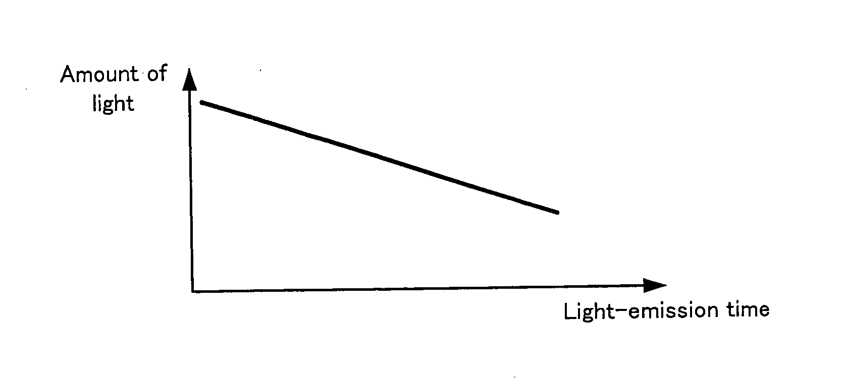
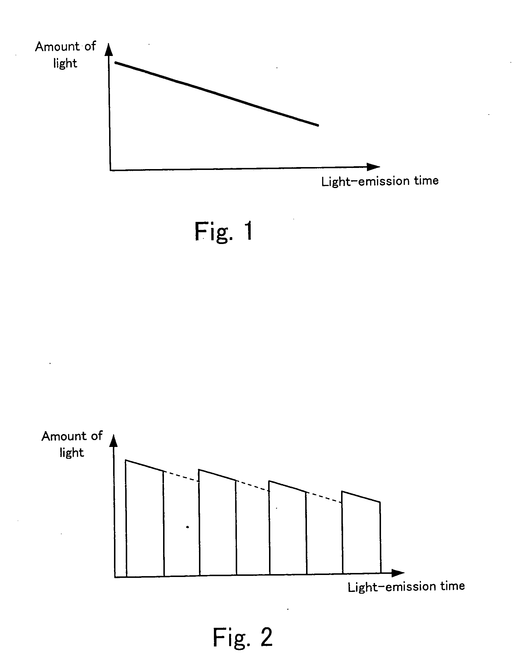
a technology of image-taking apparatus and light source, which is applied in the direction of shutters, instruments, and exposure control, etc., can solve the problems of increasing the number of shootings, the amount of light emitted at one shooting gradually decreases, and the amount of light emitted at each shooting time during continuous shooting gradually decreases, so as to achieve control of the shooting interval and higher precision

Inactive Publication Date: 2007-05-17
FUJIFILM CORP
View PDF6 Cites 5 Cited by
  • Summary
  • Abstract
  • Description
  • Claims
  • Application Information

AI Technical Summary

Benefits of technology

[0053] This makes it possible to control the shooting interval with higher precision because the light-amount monitor monitors the amount of light emitted from the LED at each shooting.
[0054] As described above, the invent

Problems solved by technology

However, LEDs have such a problem that the amount of light emitted from an LED gradually decreases with the passage of light-emission time.
When light emission of an LED having such a tendency is used for continuous shooting or multiple exposures, there arises not only a problem that the amount of light emitted at one shooting gradually decreases over the time as shown in FIG. 1, but also another problem that the amount of light emi

Method used


Image

  • Image-taking apparatus
  • Image-taking apparatus
  • Image-taking apparatus

Examples


Embodiment Construction

[0069] Embodiment(s) of the present invention will be described with reference to the drawings.

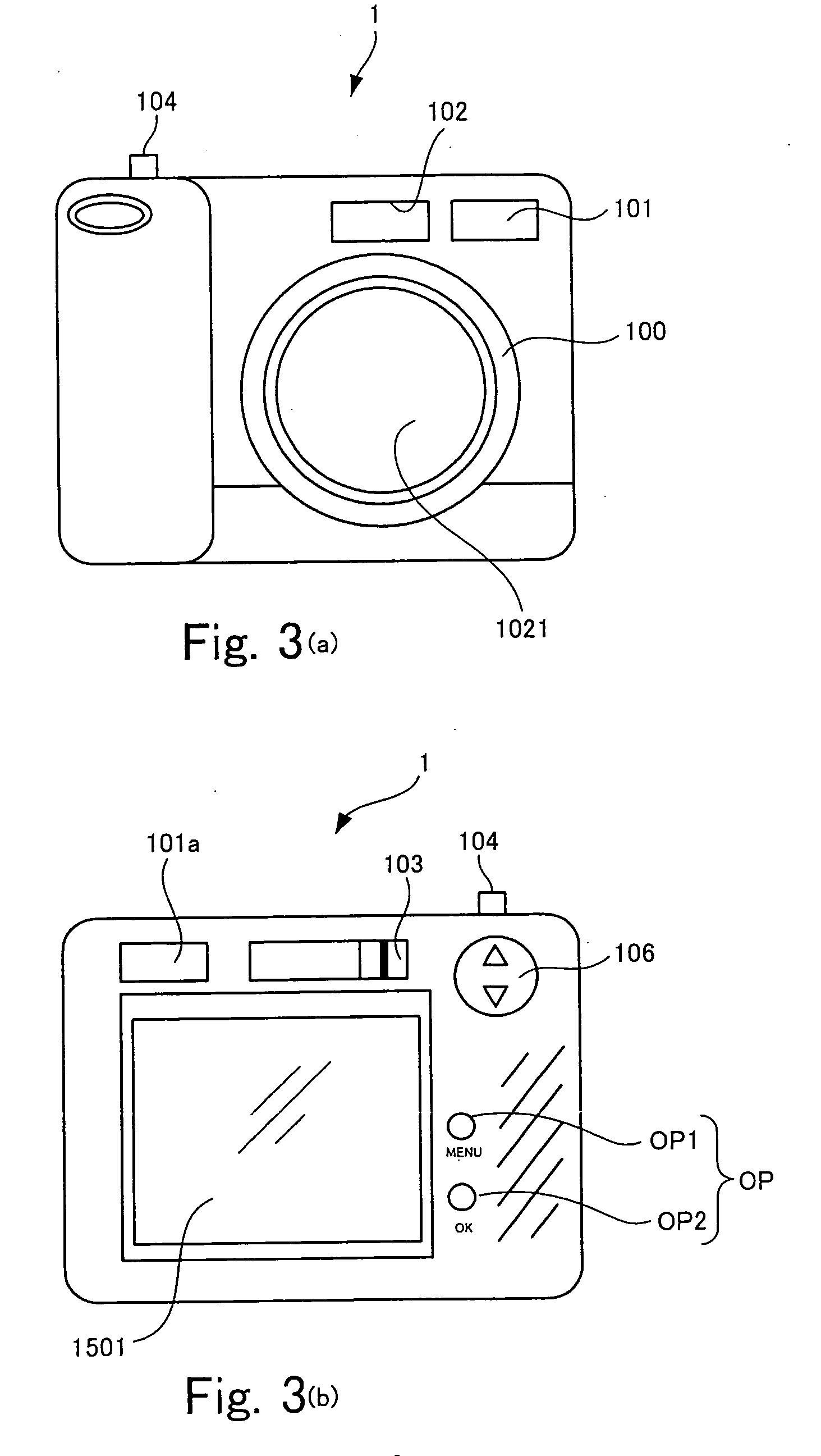
[0070] FIGS. 3(a) and 3(b) are external views of a digital camera 1 according to an embodiment of the invention.

[0071] FIGS. 3(a) and 3(b) illustrate the front and the back of the digital camera 1, respectively.

[0072] As shown in FIG. 3(a), the digital camera 1 has a lens barrel 100 on its front face. The barrel 100 has a built-in shooting lens group 1021. In addition, a light-emission window 102 is disposed above the lens barrel 100, and a finder 101 is disposed next to the light-emission window 102. Fill light is emitted through the light-emission window 102 toward a subject, when a system control circuit that will be described later determines that emission of fill light is necessary. Further, a release button 104 is disposed on the top face of the body of the digital camera 1.

[0073] As shown in FIG. 3(b), a display screen 1501 is disposed on the back face of the digital camera 1. A...


PUM


Abstract

An image-taking apparatus includes: an A/D conversion circuit having an amplifier that is capable of amplifying image signals per shooting frame; and a gain changer that changes the gain of the amplifier. The apparatus causes the gain changer to increase the gain of the amplifier up to a level that compensates for a gradual decrease in the amount of light emitted from LEDs that occurs during continuous shooting. As a result, the amplitude level of every image signal is made constant and thus, replayed images of the same brightness shot during the continuous shooting are obtained.

Description

BACKGROUND OF THE INVENTION [0001] 1. Field of the Invention [0002] The present invention relates to an image-taking apparatus that includes an imaging device and an image-taking optical system, and generates image signals representing a subject image formed on the imaging device through the image-taking optical system. [0003] 2. Description of the Related Art [0004] There have been proposed techniques for employing a light-emitting diode (LED) as a light source in place of a xenon tube (see Japanese Patent Application Publications No. 2005-128413 and No. 2005-134711 for example). Use of the LED eliminates the constraints of the time for recharging a main capacitor and thus, it is possible to emit shooting fill light at any desired time. [0005] Generally, when subject luminance is insufficient in multiple exposures or continuous shooting, fill light is emitted in a pulse at every shooting time so that subject luminance for each shooting is secured. If an LED is used in this type of ...

Claims


Application Information

Patent Timeline
IPC IPC(8): G03B15/03
CPCG03B15/03
Inventor TOKIWA, KENTAROAWAZU, KOUHEI
Owner FUJIFILM CORP
Why Eureka
Try Eureka