Liquid crystal display device

a liquid crystal display and transparent technology, applied in non-linear optics, instruments, optics, etc., can solve the problem of conspicuous boundary between two directions, and achieve the effect of improving the difference between reflectance and color ton

Inactive Publication Date: 2007-05-31
JAPAN DISPLAY CENTRAL CO LTD
View PDF8 Cites 33 Cited by
  • Summary
  • Abstract
  • Description
  • Claims
  • Application Information

AI Technical Summary

Benefits of technology

[0010] It is an object of the present invention to improve the differences in reflectance ratio and color tone between the image area that performs translucent display and the dummy area owing to the structural difference between the pixels thereof, and to make the boundary between the image area and the dummy area inconspicuous in the case of performing the reflection display of the white color.
[0012] In this invention, in the color filters of at least the same one color, the size ratio of the transparent areas in the reflection pixels with respect to the reflection areas therein is larger than a size ratio of the transparent areas in the translucent pixels with respect to the reflection areas therein. In such a way, brightness of the display is balanced by adjusting quantities of transmission light through the transparent areas in the reflection pixels with respect to quantities of reflection light generated unexpectedly on the transmission areas in the translucent pixels. Moreover, since degrees of whiteness in the translucent pixels and the reflection pixels are approximated to each other, differences in reflectance ratio and color tone between the image area and the dummy area can be improved, and a boundary between both thereof can be made inconspicuous.
[0014] In this invention, the size of the reflection areas of the reflection pixels is equalized to the size of the reflection areas of the translucent pixels, thus making it possible to easily adjust the size ratios only by the sizes of the transparent areas of the reflection pixels and the translucent pixels.
[0016] In this invention, the size of the reflection areas of the reflection pixels is larger than the size of the reflection areas of the translucent pixels, and in the blue color filter, the size ratio of the transparent areas provided in the reflection pixels with respect to the reflection areas provided therein is larger than the size ratio of the transparent areas provided in the translucent pixels with respect to the reflection areas provided therein. In such a way, the brightness is ensured by transmission light though the transparent areas of the reflection pixels. Moreover, in each of the red and green color filters, the size ratio of the transparent areas provided in the reflection pixels with respect to the reflection areas provided therein is smaller than the size ratio of the transparent areas provided in the translucent pixels with respect to the reflection areas provided therein. In such a way, degrees of whiteness of both of the reflection pixels and the translucent pixels are adjusted, thus making it possible to improve differences in reflectance and color tone between the reflection areas and the translucent display areas.

Problems solved by technology

Therefore, differences occur in reflectance and color tone between the image area and the dummy area, causing a problem that, in the case of performing the reflection display of the white color, a boundary therebetween becomes conspicuous.

Method used


Image

  • Liquid crystal display device
  • Liquid crystal display device
  • Liquid crystal display device

Examples


first embodiment

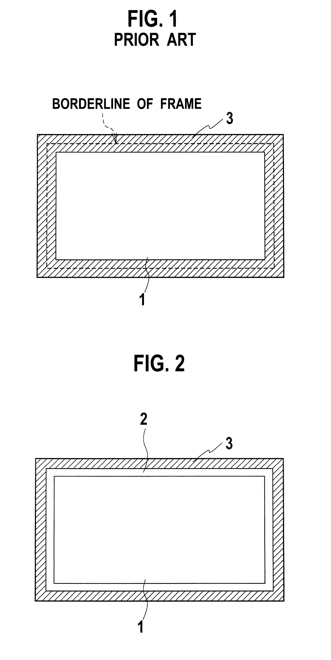
[0025] As shown in a plan view of FIG. 2, in a liquid crystal display device of a first embodiment, a dummy area 2 that always displays white color is provided on a peripheral area between an image area 1 and a frame-like black mask 3.

[0026] On the image area 1, a plurality of translucent pixels that have reflection areas and transmission areas are arrayed. In the transmission areas, an image is displayed by a light transmission mode. Meanwhile, in the reflection area, an image is displayed by a light reflection mode using the external light.

[0027] On the dummy area 2, a plurality of reflection pixels that have only reflection areas are arrayed. In the reflection areas, the white color is always displayed by a light reflection mode using the external light. Note that, in this liquid crystal display device, the white color is displayed on both of the image area 1 and the dummy area 2 when a voltage is not applied to a liquid crystal layer (normally white display).

[0028] Next, a de...

second embodiment

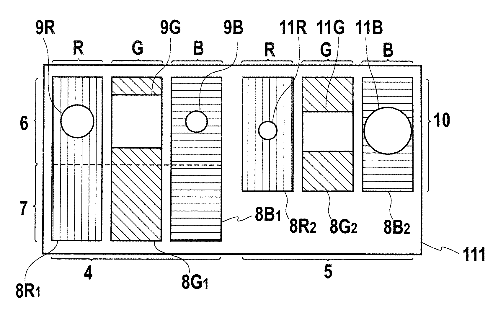
[0048] A configuration of a liquid crystal display device in a second embodiment is basically similar to that described in the first embodiment. Different points of the second embodiment from the first embodiment are the following two. The first point is that the size S of the reflection area 10 of the reflection pixel 5 is larger than the size S′ of the reflection area 6 of the translucent pixel 4. The second point is that, in the blue color filters 8B, the size ratio SCF / S obtained in such a manner that the size of the transparent area in the reflection pixel 5 is divided by the size of the reflection area therein is larger than the size ratio S′CF / S′ in the translucent pixel 4, and in each of the red and green color filters 8R and 8G, the size ratio SCF / S obtained in such a manner that the size of the transparent area in the reflection pixel 5 is divided by the size of the reflection area therein is smaller than the size ratio S′CF / S′ in the translucent pixel 4. A description wil...


PUM

PropertyMeasurementUnit
transparentaaaaaaaaaa
sizeaaaaaaaaaa
colorsaaaaaaaaaa

Abstract

In order to make a boundary inconspicuous, which is located between an image area which displays an image by translucent pixels and a dummy area which always displays a white color by reflection pixels, a size ratio of transparent areas in color filters of the reflection pixels with respect to reflection areas therein is made larger than a size ratio of transparent areas in color filters of the translucent pixels with respect to reflection areas therein. In such a way, brightness of the display is balanced by adjusting quantities of transmission light through the transparent areas of the reflection pixels with respect to quantities of reflection light generated unexpectedly on transmission areas of the translucent pixels. Then, degrees of whiteness in the translucent pixels and the reflection pixels are approximated to each other.

Description

CROSS-REFERENCE TO RELATED APPLICATIONS [0001] This application is based upon and claims the benefit of priority from Japanese Patent Application No. 2005-337722 filed on Nov. 22, 2005; the entire contents of which are incorporated herein by reference. BACKGROUND OF THE INVENTION [0002] 1. Field of the Invention [0003] The present invention relates to a translucent liquid crystal display device which displays an image by both of a light reflection mode and a light transmission mode. [0004] 2. Description of the Related Art [0005] In general, in the field of a mobile information terminal such as a cellular phone and a mobile music player, a liquid crystal display device is used for displaying an image and a character. In particular, a translucent liquid crystal display device that displays an image by a light reflection mode and a light transmission mode has high visibility both indoors and outdoors. As the translucent liquid crystal display device, for example, the one disclosed in ...

Claims


Application Information

Patent Timeline
Patent Type & Authority Applications(United States)
IPC IPC(8): G02F1/1335
CPCG02F1/133371G02F1/133514G02F1/133555G02F2001/133388G02F2201/52G02F1/133388G02F1/1335
Inventor TAGO, KEIJITABATAKE, HIROSHIKIMURA, HIROYUKIIIZUKA, TETSUYA
Owner JAPAN DISPLAY CENTRAL CO LTD
Why Eureka
Try Eureka