Mounting device for mobile information terminal, and mobile information terminal

a technology for mobile information terminals and mounting devices, which is applied in the direction of transmission, transportation and packaging, substation equipment, etc., can solve the problems of difficult to say that a user can be understandably notified of the processing status of the mounting device, and a part of the surface is affected, so as to prevent accidental ejection of the mobile information terminal from the mounting device during processing and avoid discontinuation of processing due to ejection

Active Publication Date: 2007-06-21
PANASONIC INTELLECTUAL PROPERTY CORP OF AMERICA
View PDF14 Cites 41 Cited by
  • Summary
  • Abstract
  • Description
  • Claims
  • Application Information

AI Technical Summary

Benefits of technology

[0019] According to the construction described above, accidental ejection of the mobile information terminal from the mounting device during processing can be prevented, and discontinuation of the processing due to the ejection can be avoided.
[0020] Therefore, not only the user of the mobile information terminal, but also a malicious third person cannot eject the mobile information terminal. Especially in the case where the mounting device is installed in a public place, such as a store, and the mobile information terminal is mounted to the mounting device, the mobile information terminal can be protected from theft. As a result, attending or keeping a lookout for the mobile information device not to be stolen is not necessary.

Problems solved by technology

However, even with the reference 1, the mounting device has not gone beyond the stage of the mere adapter from the point of view of operability for the mounting device.
Therefore, it is hard to say that a user can be understandably notified of processing status of the mounting device.
However, in the art mentioned above, when communication and charging are carried out simultaneously, the mobile terminal will be ejected at the time of the completion of charging, communication will be interrupted, and it is inconvenient.
However, the prior art cuts out a part of the surface of the mounting device, and only exposes a part of the LCD.

Method used


Image

  • Mounting device for mobile information terminal, and mobile information terminal
  • Mounting device for mobile information terminal, and mobile information terminal
  • Mounting device for mobile information terminal, and mobile information terminal

Examples


embodiment 1

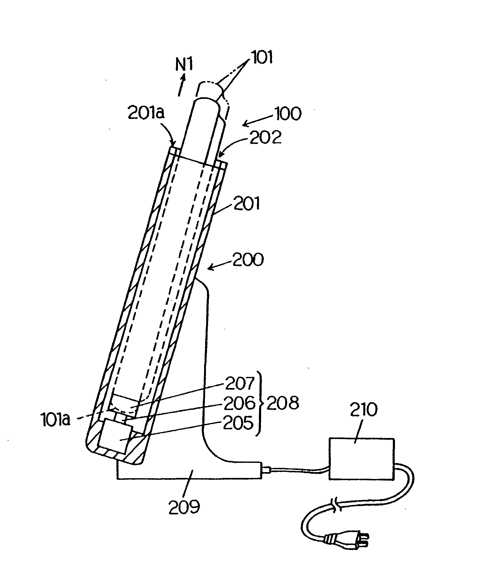
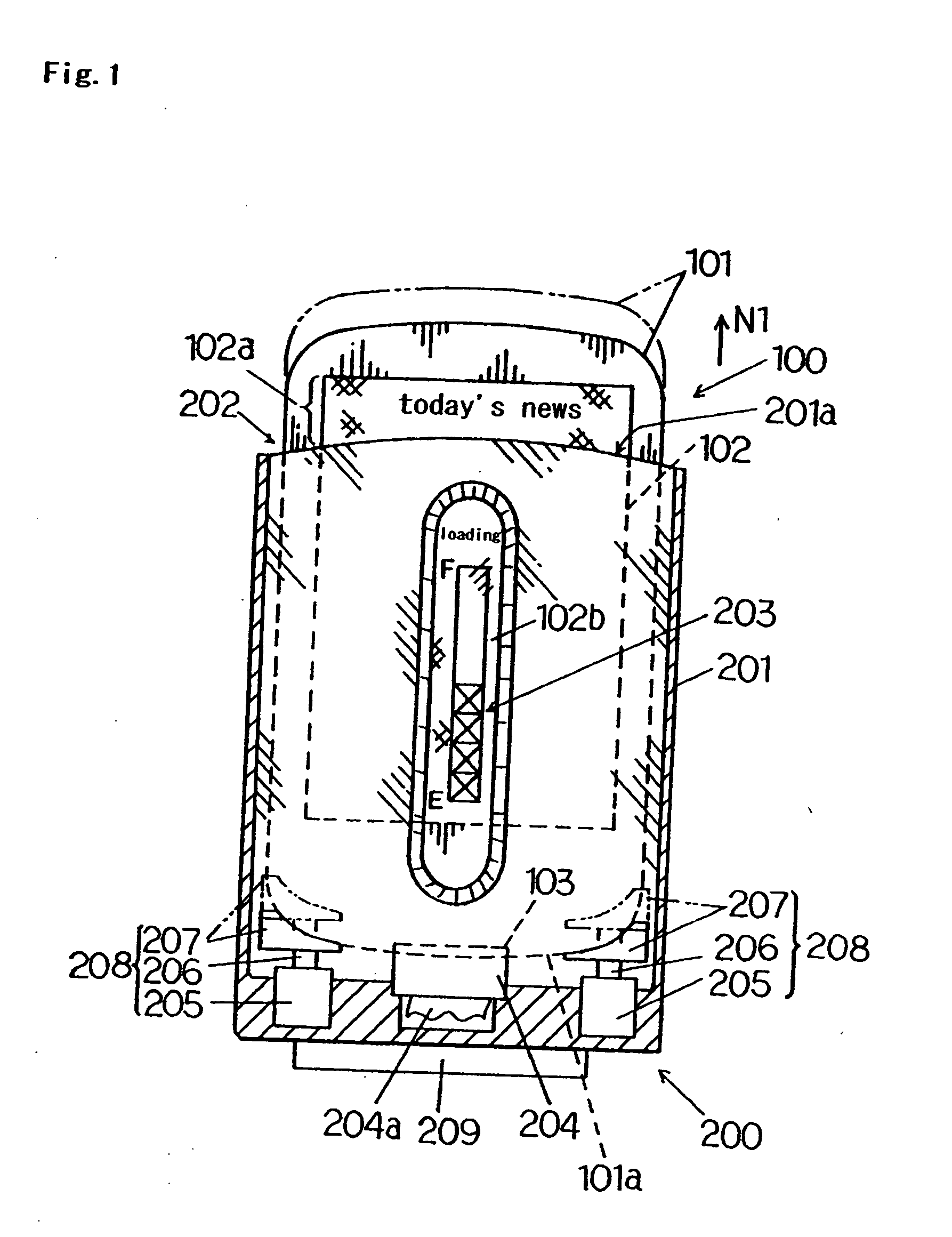
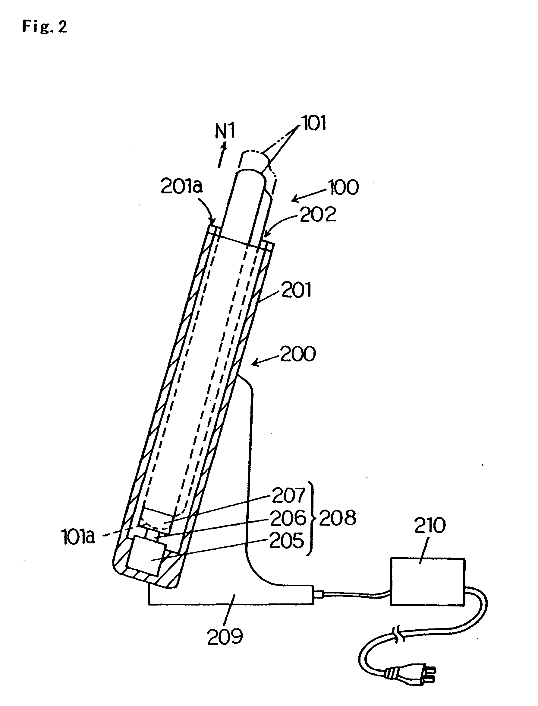
[0061]FIG. 1 is the drawing illustrating the front view of the mounting device and the mobile information terminal in the first embodiment of the present invention.

[0062] As shown in FIG. 1, a mounting device 200 comprises a case 201 and a support unit 209.

[0063] The case 201, which is a shape of a box, possesses an opening portion at the upper edge. The opening portion is an insertion inlet 202 for a mobile information terminal 100.

[0064] The mobile information terminal 100 is inserted from the insertion inlet 202, and is mounted to the mounting device 200 in a freely connectable and separatable manner.

[0065] A window 203 is established in the central part of the front side of the case 201. When the mobile information terminal 100 is inserted from the insertion inlet 202, a part of a display unit 102 of the mobile information terminal 100 can be confirmed by looking from the outside via the window 203.

[0066] The window 203 may be a complete hole, or may be sealed off by transp...

embodiment 2

[0112] The second embodiment of the present invention is explained referring to FIG. 6 to FIG. 8.

[0113] The present embodiment differs in that the lock mechanism has been established, as compared to the first embodiment of the present invention.

[0114] Thus, a notch 112 is formed in the side unit as enlarged and shown in FIG. 6.

[0115] A part of the case 201 is made to be expanded, and a storage unit 201b is formed. Then, a solenoid 212 is arranged inside of the storage unit 201b, and a rod 213 of the solenoid 212 is made to be turned sideways so as to face the notch 112.

[0116] In the state where the mobile information terminal 100 is inserted into the insertion inlet 202 and the connector 103 and the connector 204 are connected (refer to solid lines), the location of the rod 213 and the location of the notch 112 are made to be matched.

[0117] At this time, when the solenoid 212 is operated and the rod 213 is made to project from the solid line position to a dashed line position, ...

embodiment 3

[0130] The first embodiment and the second embodiment are applicable also to a business-use mounting device, as shown in FIGS. 9 and 10.

[0131]FIG. 9 shows the appearance of the business-use mounting device in such an application, and FIG. 10 illustrates an example of contents of a display.

[0132] Especially, it is desirable to apply the second embodiment to this application.

[0133] For example, when the present embodiment is applied to data write-in devices (KIOSK terminal, etc.) which will be installed in public places (for example, a shop front, a station, etc.) to sell a digital content, theft of a mobile information terminal can be prevented without escorting of a user during processing.


PUM


Abstract

A mounting device includes a case that has an insertion inlet for a mobile information terminal, a connector that establishes electrical connection to the mobile information terminal inserted in the insertion inlet, and an ejection mechanism that ejects the mobile information terminal after completion of processing through the connector. After the completion of the processing, by an action of the ejection mechanism, the mobile information terminal is popped up from the mounting device, and a user is understandably notified of the completion of the processing.

Description

[0001] This application is a divisional application of application Ser. No. 10 / 682,934, filed Oct. 14, 2003.BACKGROUND OF THE INVENTION [0002] 1. Field of the Invention [0003] The present invention relates to a mounting device to which a mobile information terminal is mounted, and an art related thereto. [0004] 2. Description of the Related Art [0005] As electronic-communications technology has advanced in recent years, small-sized, lightweight, and thin-sized display devices (for example, LCD, organic electroluminescence, electronic paper, etc.) have spread out widely, and mobile information terminals (for example, PDA (Personal Digital Assistant), etc.) with these display devices and mounting devices for such mobile information terminals have been used practically. [0006] In general, such a mounting device is only an adapter that makes an adjustment with a charging unit or a connection interface. [0007] As for this point, contrivance, which improves a function of the mounting devi...

Claims


Application Information

Patent Timeline
Patent Type & Authority Applications(United States)
IPC IPC(8): H04M1/00H02J7/00
CPCH02J7/0044
Inventor HAMASAKI, SHOGOIINO, DAISUKEFUJIMOTO, MAKOTOWATANABE, KAZUHISASASO, ATSUSHIKOBAYASHI, NORIHIKO
Owner PANASONIC INTELLECTUAL PROPERTY CORP OF AMERICA
Why Eureka
Try Eureka