Threaded suture anchor with starting pitch

a technology of suture anchor and starting pitch, which is applied in the field of suture anchors, can solve the problems of excessive force, excessive effort required to insert the suture anchor along the thread, and the above-described prior art suture anchor is difficult to secure to the bone, so as to facilitate the insertion of the suture anchor and facilitate the insertion of the bon

Inactive Publication Date: 2007-06-21
ARTHREX
View PDF26 Cites 47 Cited by
  • Summary
  • Abstract
  • Description
  • Claims
  • Application Information

AI Technical Summary

Benefits of technology

[0010] The suture anchor of the present invention overcomes disadvantages of the prior art, such as those noted above, by providing a suture anchor having a thread spiralling helically around a central body and having a configuration that facilitates insertion of the suture anchor into the bone by providing a gradual change from a starting pitch (i.e, a thread disposed along the longitudinal axis of the suture anchor at the distal end of the anchor) to a helical or spiral pitch around the central body. By providing the starting pitch at the distal end of the suture anchor, the suture anchor can be inserted more readily into the bone without the need for additional or excessive force.
[0011] The present invention also provides a suture anchor and driver assembly for driving the anchor into bone. Advantageously, the suture anchor of the present invention is provided with threads formed in the shape of a corkscrew, to provide an increased percentage of thread surface area for each turn of the screw, as compared with known suture anchors, thus providing increased pull-out strength, and a decreased tendency for back-out. The driver for driving the corkscrew anchor may be provided with a cleat on the side of the handle. Suture threaded through the cannulated driver can be wrapped around the cleat and fixed for shipping in a slot in the cleat. The suture anchor and driver assembly can be shipped (pre-loaded with suture) as a sterile, surgery-ready unit.

Problems solved by technology

The above-described prior art suture anchors are difficult to secure to the bone, at least initially.
For example, following an initial hammering of the suture anchor into the bone, excessive effort may be required to insert the suture anchor along the thread.
Use of excessive force may increase the risk of injury to a patient from insertion of the suture anchor especially in softer bone sites, such as cancellous bone, or in bone tissue that has become compromised, such as in osteoporotic bone sites.
These bone types may present a limited range of specific fixation points that are available to the surgeon.

Method used


Image

  • Threaded suture anchor with starting pitch
  • Threaded suture anchor with starting pitch
  • Threaded suture anchor with starting pitch

Examples


Embodiment Construction

[0019] In the following detailed description, reference is made to various specific embodiments in which the invention may be practiced. These embodiments are described with sufficient detail to enable those skilled in the art to practice the invention, and it is to be understood that other embodiments may be employed, and that structural and logical changes may be made without departing from the spirit or scope of the present invention.

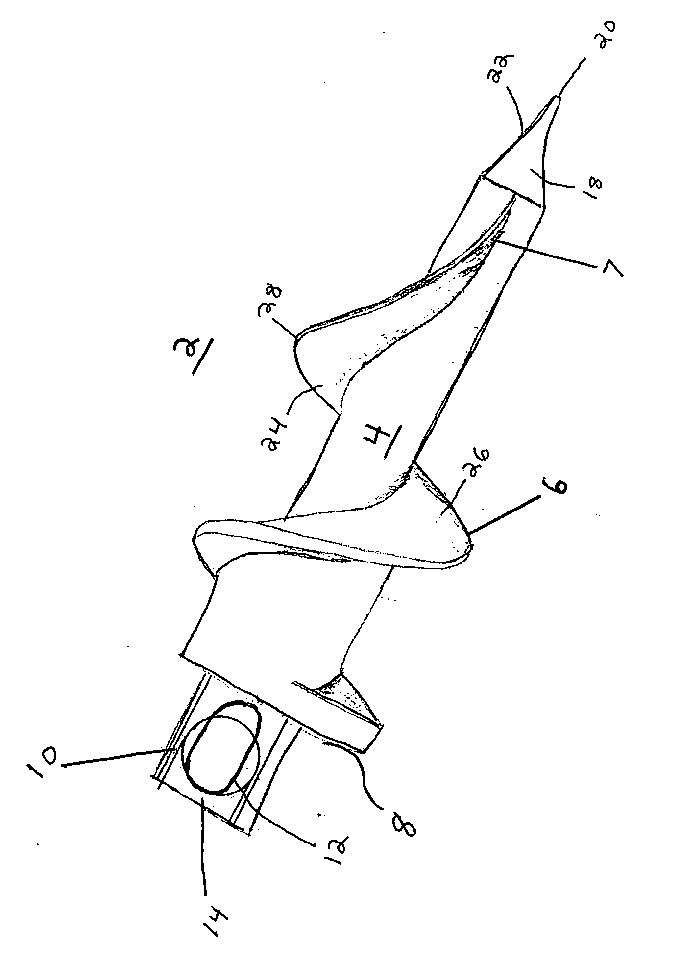
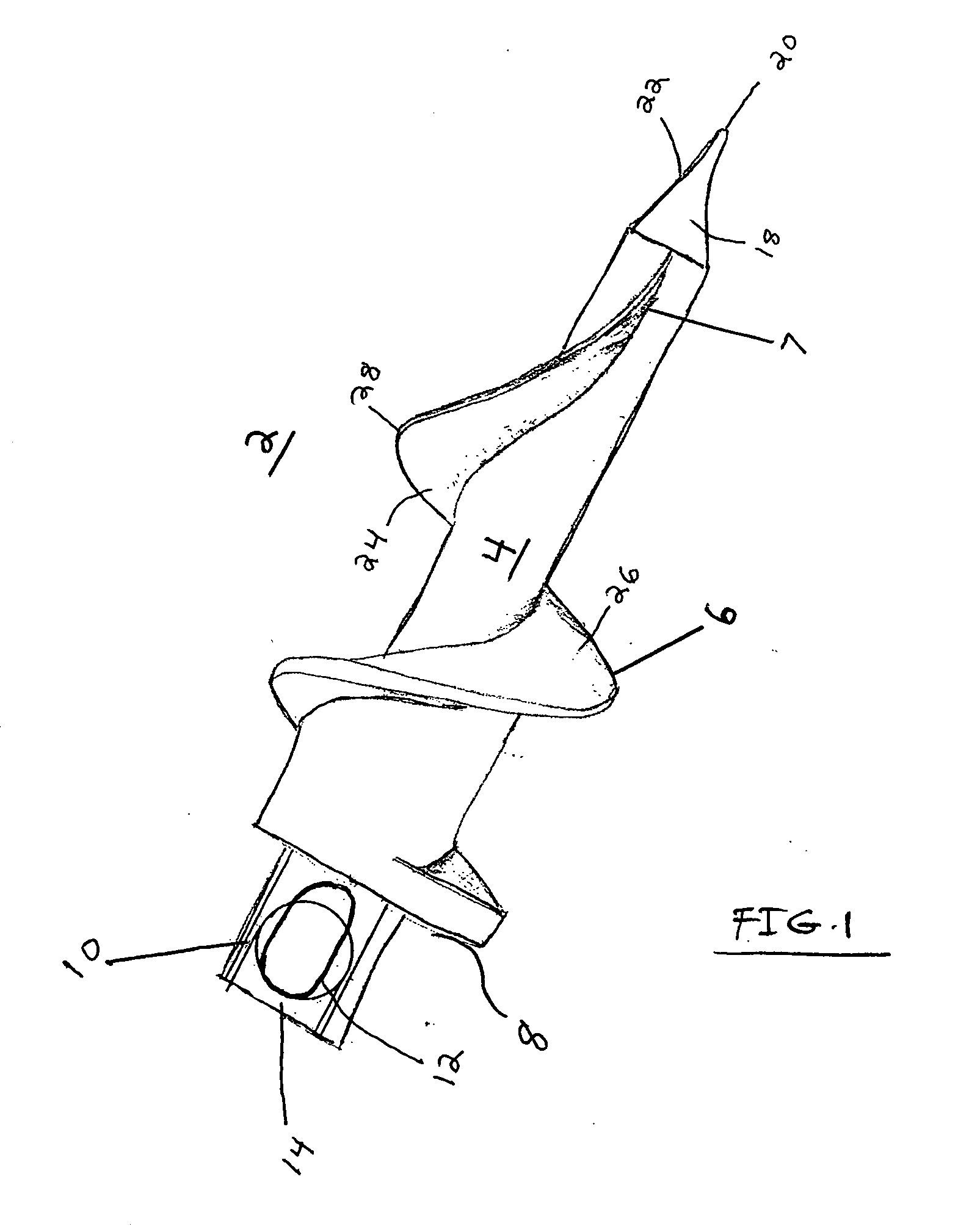
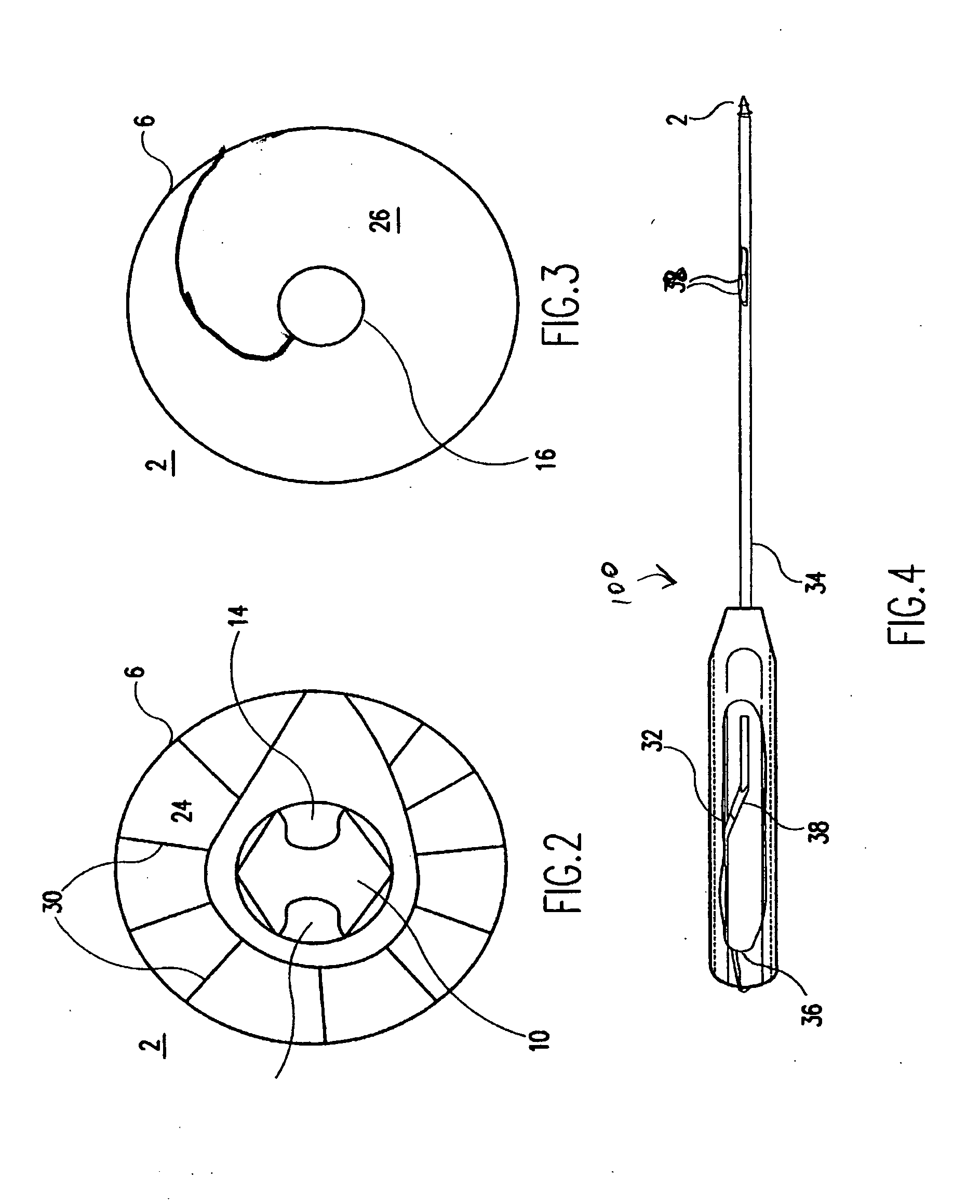
[0020] Referring now to the drawings, where like elements are designated by like reference numerals, FIGS. 1-6 illustrate exemplary embodiments of suture anchors of the present invention. As explained in detail below, the suture anchors of the present invention have a thread spiralling helically around a central body and includes a configuration that facilitates insertion of the suture anchor into the bone by providing a gradual change from a starting pitch (i.e, a thread disposed along the longitudinal axis of the suture anchor at the distal end of...


PUM


Abstract

A suture anchor has a continuous thread spiralling around a tapering central core. At the distal end of the thread, the suture anchor has a starting pitch to facilitate insertion of the anchor into bone. The proximal end of the suture anchor receives at least one strand of suture. At the proximal end, the suture anchor has a large thread surface per turn of thread.

Description

CROSS-REFERENCE TO RELATED APPLICATIONS [0001] This application claims the benefit of U.S. Provisional Application Ser. No. 60 / 750,362, filed Dec. 15, 2005, the entire disclosure of which is incorporated by reference herein.BACKGROUND OF THE INVENTION [0002] 1. Field of the Invention [0003] The present invention relates to an apparatus and method for anchoring surgical suture to bone. More specifically, the present invention relates to a suture anchor having a thread with a starting pitch geometry configured to permit easier insertion into bone. [0004] 2. Description of the Related Art [0005] When soft tissue tears away from bone, reattachment becomes necessary. Various devices, including sutures alone, screws, staples, wedges, and plugs have been used to secure soft tissue to bone. Recently, various types of threaded suture anchors have been developed for this purpose. [0006] Suture anchors have been developed and designed to be inserted into a pre-drilled hole. Other suture anchor...

Claims


Application Information

Patent Timeline
Patent Type & Authority Applications(United States)
IPC IPC(8): A61B17/58
CPCA61B17/0401A61B17/863A61B2017/0409A61B2017/0414A61B2017/044
Inventor DREYFUSS, PETER J.
Owner ARTHREX
Why Eureka
Try Eureka