Video Projector

a technology for projectors and video, applied in projectors, instruments, optics, etc., can solve the problems of rarely increasing the power consumption of video projectors due to cooling fans, and achieve the effects of increasing the cooling capacity of blower fans, preventing the increase of manufacturing costs of video projectors, and increasing the quantity of cooling air

Inactive Publication Date: 2007-11-29
FUNAI ELECTRIC CO LTD
View PDF12 Cites 40 Cited by
  • Summary
  • Abstract
  • Description
  • Claims
  • Application Information

AI Technical Summary

Benefits of technology

[0011]According to such a configuration, elements of the optical engine provided in the first portion are cooled by air flow which is sucked by the blower fan, and elements of the optical engine provided in the second portion are cooled by a part of the cooling air generated by the blower fan, so that all the elements that constitute the optical engine are cooled simultaneously with the light source without increasing the quantity of the cooling air generated by the blower fan. I...

Problems solved by technology

Furthermore, the power consumption of the vide...

Method used


Image

  • Video Projector
  • Video Projector
  • Video Projector

Examples


Embodiment Construction

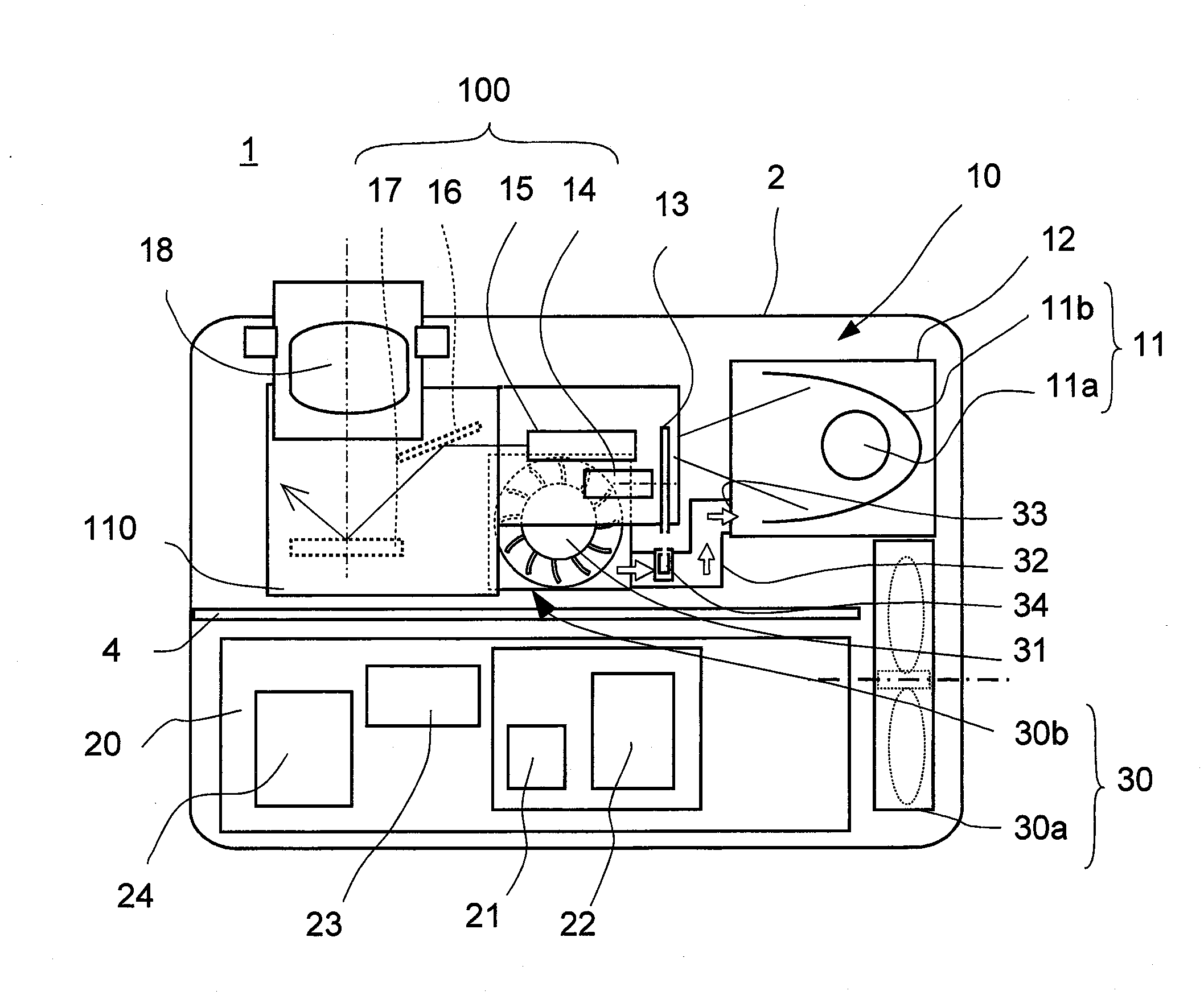
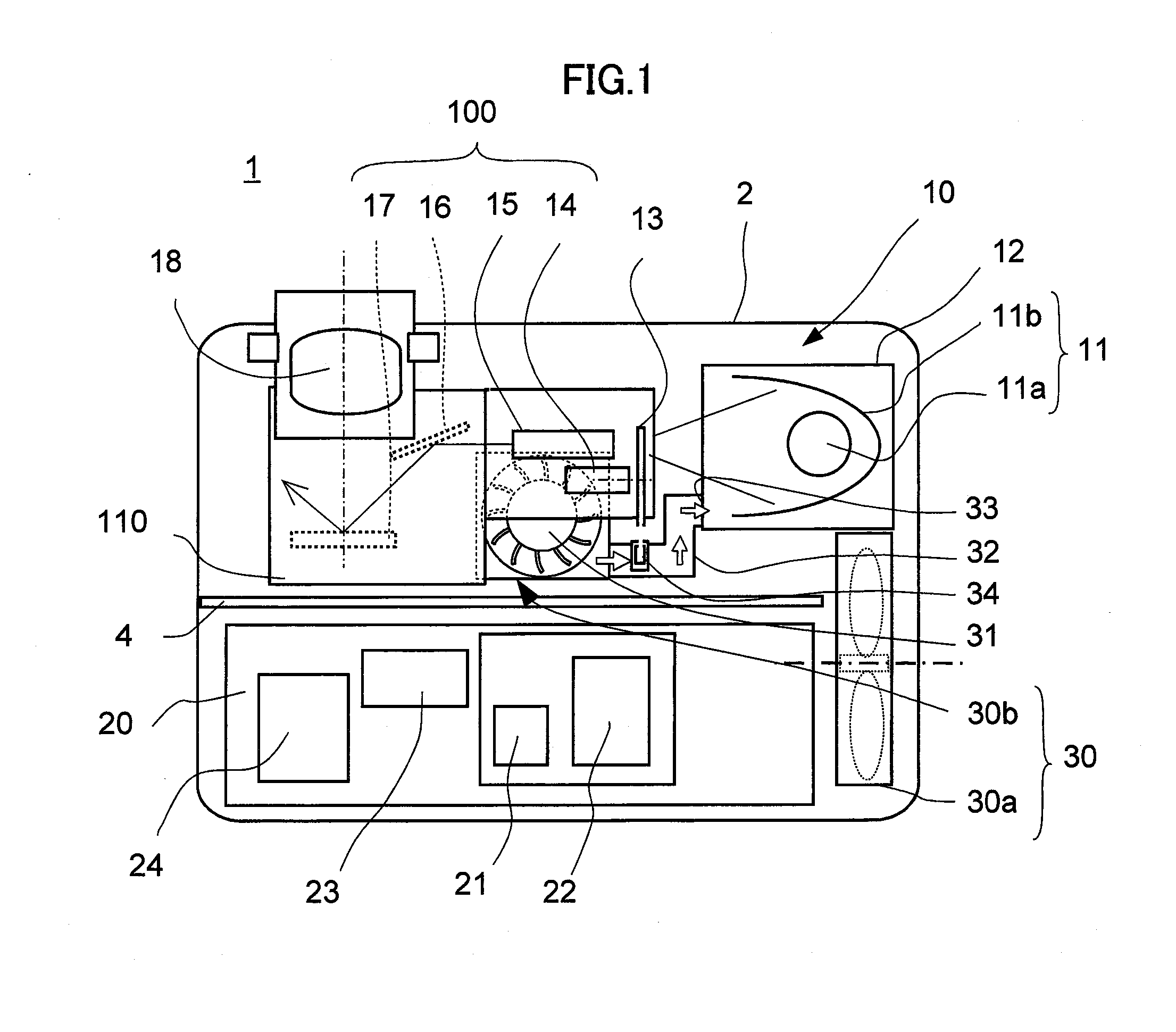
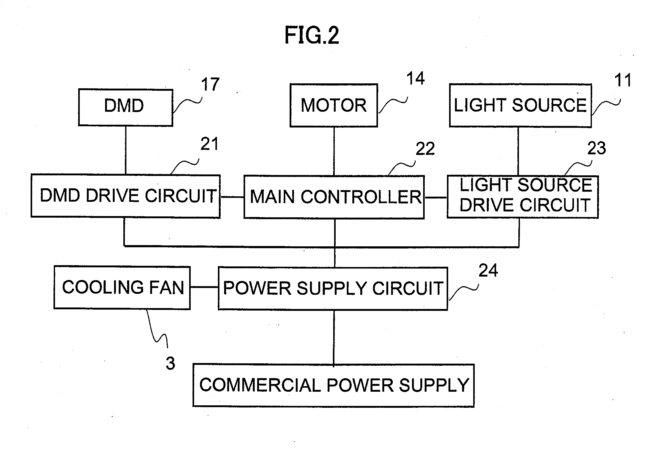
[0018]A video projector in accordance with an embodiment of the present invention is described with reference to the drawings. FIG. 1 shows a configuration of a video projector 1 in accordance with the present preferred embodiment. FIG. 2 shows a block configuration of the video projector 1. The video projector 1 is used to project an enlarged image on a screen which is located in front of the video projector 1 by using image signals (image data) outputted from a personal computer, a video camera, or the like. The video projector 1 is schematically comprised of an image forming unit 10 that is disposed at a front portion of a housing 2 and forms an image or images with using the image signals inputted from outward, and a control unit 20 that is disposed at a rear portion of the housing 2, processes the image signals inputted from the outward and controls the image forming unit 10.

[0019]As can be seen from FIG. 1, the video projector 1 comprises a light source 11 such as a discharge ...


PUM


Abstract

A video projector (1) comprises a light source (11) enclosed in a lamp box (12), an optical engine (100) including a color wheel (13), an optical tunnel (15), a mirror (16) and a DMD (Digital Micro-mirror Device) (17), and a blower fan (30a) disposed in the vicinity of the light source (11) and below the optical engine (100). The blower fan (30b) sucks air through a portion of the optical engine (100) where the optical tunnel (159 and so an are provided except the color wheel (13), generates a cooling air and exhausts a part of the cooling air toward the color wheel (13) and the rest of the cooling air toward the light source (11), so that the elements of the optical engine (100) and the light source (11) are cooled by the blower fan (30b) simultaneously.

Description

BACKGROUND OF THE INVENTION[0001]1. Field of the Invention[0002]The present invention relates to a video projector which projects images on an external screen.[0003]2. Description of the Related Art[0004]In a video projector, which projects images on a screen disposed in front of the video projector on the basis of image signals outputted from a personal computer, for example, a discharge lamp is conventionally used as a light source. Since the light emitting portion of the light source generates heat following to the light emission, it is cooled by a cooling air generated by a blower fan so as to maintain a proper temperature not to be too high-temperature. In addition, elements such as a color wheel and so on, which are to be heated by the light beam emitted from the light source during the operation of the video projector, are cooled by a cooling air which is taken inside a housing of the video projector by a ventilation fan.[0005]A conventional video projector disclosed in, for ...

Claims


Application Information

Patent Timeline
IPC IPC(8): G03B21/18
CPCG03B21/16
Inventor DOI, NAOHITOOCHI, MASAKI
Owner FUNAI ELECTRIC CO LTD
Why Eureka
Try Eureka