Vehicle body structure

a technology for vehicles and body parts, applied in vehicle arrangements, roofs, transportation and packaging, etc., can solve the problems of affecting the efficiency of absorbing input load, and difficult to get a large closed section of reinforcement members, so as to achieve efficient absorbing the load input

Active Publication Date: 2008-01-10
NISSAN MOTOR CO LTD
View PDF8 Cites 42 Cited by
  • Summary
  • Abstract
  • Description
  • Claims
  • Application Information

AI Technical Summary

Benefits of technology

[0005]A rear door lock apparatus is arranged adjacent to and in front of an outer reinforcement member of a rear pillar. This makes it difficult to get a large closed section of the reinforcement member, and hinders improvement in efficiency of absorbing the input load.
[0007]An object of the present invention is to provide a vehicle body structure capable of securing strength and rigidity of a vehicle body structural member, and of securing a sufficiently large area / space for each of parts / equipment to be arranged in a vicinity of the vehicle body structural member.
[0008]Another object of the present invention is to provide a rear vehicle body structure in which a lower end portion of a pillar is extended to an upper portion of the wheel house, the structure enabling the pillar to efficiently absorb the load inputted from a shock absorber.
[0010]This structure makes it possible to secure strength and rigidity of a vehicle body structural member constituted of the first and second members in the respective opposing and non-opposing areas, and concurrently secure an area / space for arranging each of parts and the like in the vicinity of the vehicle body structural member.
[0012]According to this structure, the pillar can efficiently absorb the load inputted from the shock absorber.

Problems solved by technology

This makes it difficult to get a large closed section of the reinforcement member, and hinders improvement in efficiency of absorbing the input load.
A similar problem is likely to take place in a case where the vehicle has a restriction on a rear pillar layout, such as a case where another part / equipment is located in a vicinity of the rear pillar.

Method used


Image

  • Vehicle body structure
  • Vehicle body structure
  • Vehicle body structure

Examples


Embodiment Construction

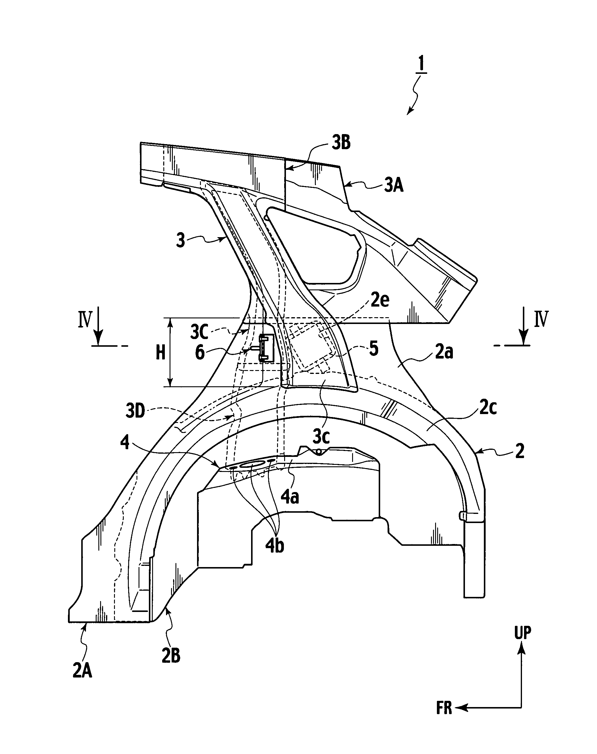
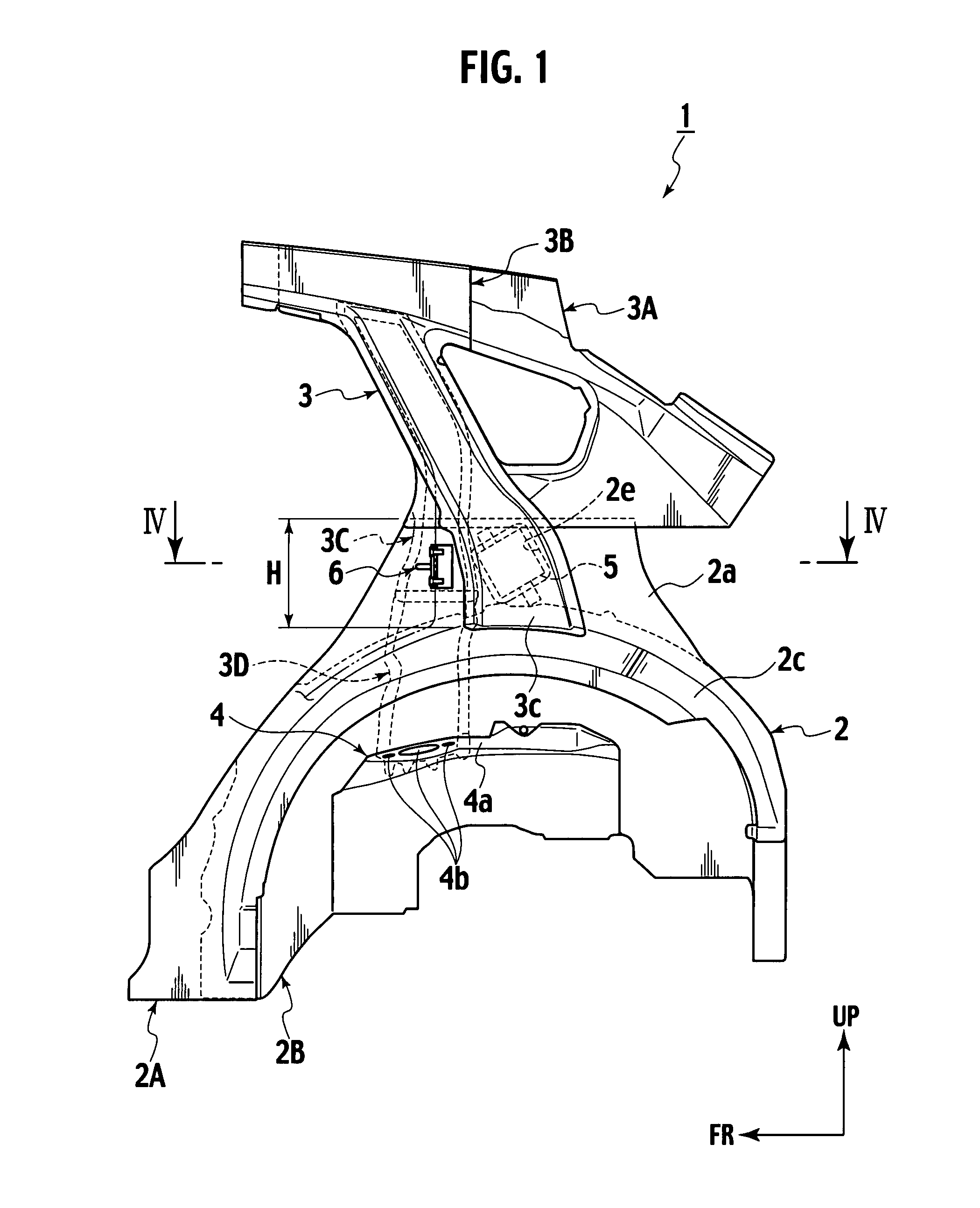
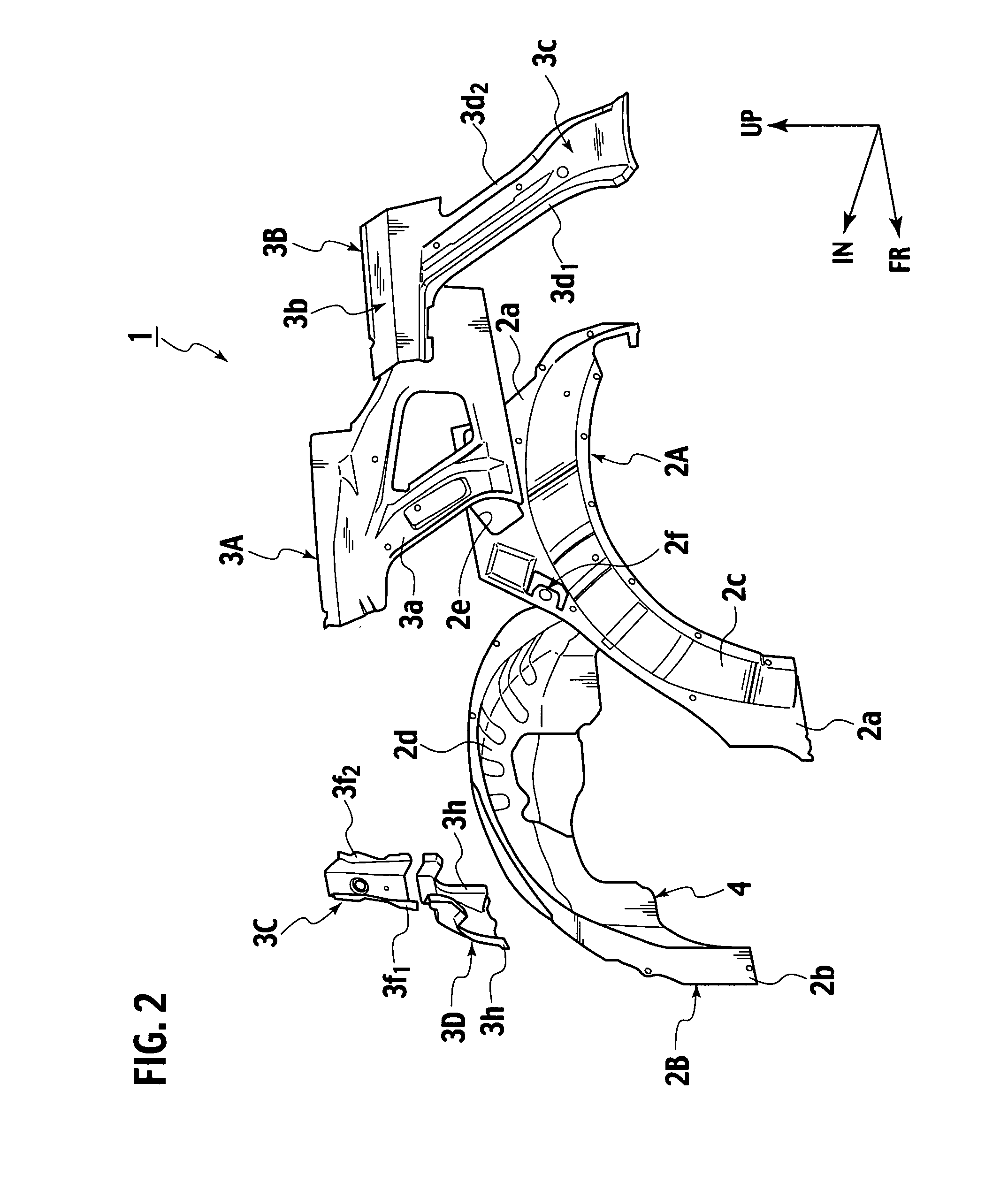
[0018]Detailed descriptions will be hereinafter provided for an embodiment of the present invention by referring to the drawings. In the drawings, it should be noted that FR denotes forward in the longitudinal direction of the vehicle; IN, toward the inside of the vehicle compartment in the vehicle transverse direction; and UP, upward.

[0019]In a vehicle body structure 1 according to an embodiment of the present invention, a lower end portion of a rear pillar 3 is extended to an upper portion of a wheel house 2, as shown in FIGS. 1 and 2. The wheel house 2 includes a wheel house outer 2A and a wheel house inner 2B. The rear pillar 3 includes a rear pillar inner 3A, a rear pillar outer reinforcement 3B, a rear pillar inner reinforcement 3C, and an inner extension 3D.

[0020]The wheel house 2 is constructed by butt-welding a joint flange 2a of the wheel house outer 2A and a joint flange 2b of the wheel house inner 2B to each other. In the wheel house 2, cover portions 2c and 2d each havi...


PUM


Abstract

A vehicle body structure comprising: first and second members each having a hat-shaped cross section including a main wall, first and second side walls extending from the main wall; an opposing area in which the opening, first side wall and second side wall of the first member are opposed to and jointed to the opening, first side wall and second side wall of the second member, respectively, with a joint surface defined therebetween; and a non-opposing area in which one of the first and second members is shifted parallel to the joint surface, so that the first side wall of the first member is opposed to and jointed to the second side wall of the second member.

Description

BACKGROUND OF THE INVENTION[0001]1. Field of the Invention[0002]The present invention relates to a vehicle body structure.[0003]2. Description of the Related Art[0004]Japanese Patent No. 3659077 discloses a rear vehicle body structure in which a lower end portion of a rear pillar is extended to a vicinity of an upper portion of a wheel house, and a brace member and a reinforcement member are used to increase the efficiency of absorbing the load from a shock absorber.SUMMARY OF THE INVENTION[0005]A rear door lock apparatus is arranged adjacent to and in front of an outer reinforcement member of a rear pillar. This makes it difficult to get a large closed section of the reinforcement member, and hinders improvement in efficiency of absorbing the input load.[0006]A source of this kind of problem is not limited to the arrangement of the rear door lock apparatus. A similar problem is likely to take place in a case where the vehicle has a restriction on a rear pillar layout, such as a cas...

Claims


Application Information

Patent Timeline
Patent Type & Authority Applications(United States)
IPC IPC(8): B62D25/00
CPCB62D25/088B62D25/04
Inventor ANDOU, TOMOTAKAABE, SEIKO
Owner NISSAN MOTOR CO LTD
Why Eureka
Try Eureka