Liquid crystal display device, driving control circuit and driving method used in same device

Active Publication Date: 2008-01-10
NEC LCD TECH CORP
View PDF9 Cites 71 Cited by
  • Summary
  • Abstract
  • Description
  • Claims
  • Application Information

AI Technical Summary

Benefits of technology

[0046]With the above configurations, by the driving control section, the backlight is turned OFF during the frame period of the input video signal in which an upper limit gray level for each of the R, G and B is set until the liquid crystal shows a response to the application of a specified voltage to the pixel region of the liquid crystal display panel, whereas, at the time of the response of the liquid crystal, the backlight is turned ON and the brightest gray level for each of the R, G, and B of the input video signal in every frame period is detected and a gray level of the input video signal is converted so that the detected brightest gray level and the above upper limit are at the same level and, during the lighting period of the backlight, the backlight is made to flash at a duty corresponding to a rate of the above brightest gray level to the above upper gray level and, therefore, a trail-leaving phenomenon in displayed moving images can be reduced and contrast of the displayed image and dynamic range of luminance can be improved.
[0047]With another configuration as above, by the driving control section, each of the light source blocks is turned ON according to a response to a liquid crystal corresponding to a light-emitting region of each of the light source blocks and the brightest gray level for each of the R, G, and B of the input video signal is detected in every frame period and a gray level of the input video signal is converted so that the detected brightest gray level and the above upper limit gray level become at the same level and, during the lighting period of each of the light source blocks, the backlight is made to flash at a duty corresponding to a rate of the brightest gray level to the above upper limit gray level and, therefore, a resolution of the displayed images is improved and trail-leaving in the displayed moving images is reduced and, further, contrast of displayed images and dynamic range of luminance are improved.
[0048]With still another configuration as above, by the driving control section,

Problems solved by technology

However, the liquid crystal panel as the related art has a problem.
That is, when black is displayed on the liquid crystal panel, if a backlight is ordinarily turned ON, leakage of light from a displaying surface of the liquid crystal panel occurs, which causes contrast to be degraded.
In addition, a CRT display panel is self-luminous and, therefore, a dynamic range of luminance can be widened by changing peak luminance according to an input video signal, whereas the liquid crystal display panel in the liquid crystal display device is non-luminous and, as a result, widening of a dynamic range of luminance is difficult.
Another problem is that, when moving images are displayed by the liquid cryst

Method used


Image

  • Liquid crystal display device, driving control circuit and driving method used in same device
  • Liquid crystal display device, driving control circuit and driving method used in same device
  • Liquid crystal display device, driving control circuit and driving method used in same device

Examples


Example

First Embodiment

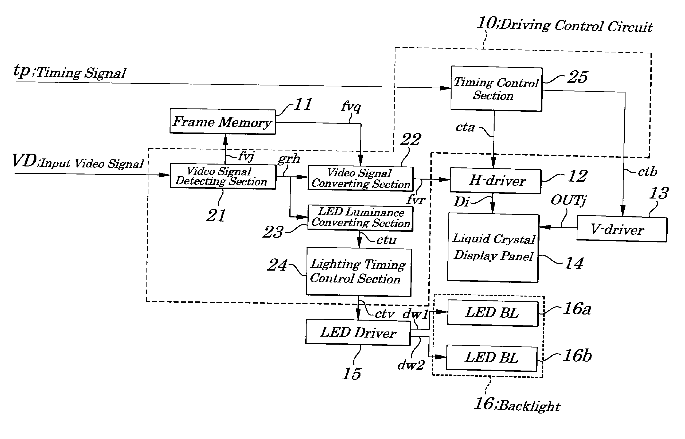
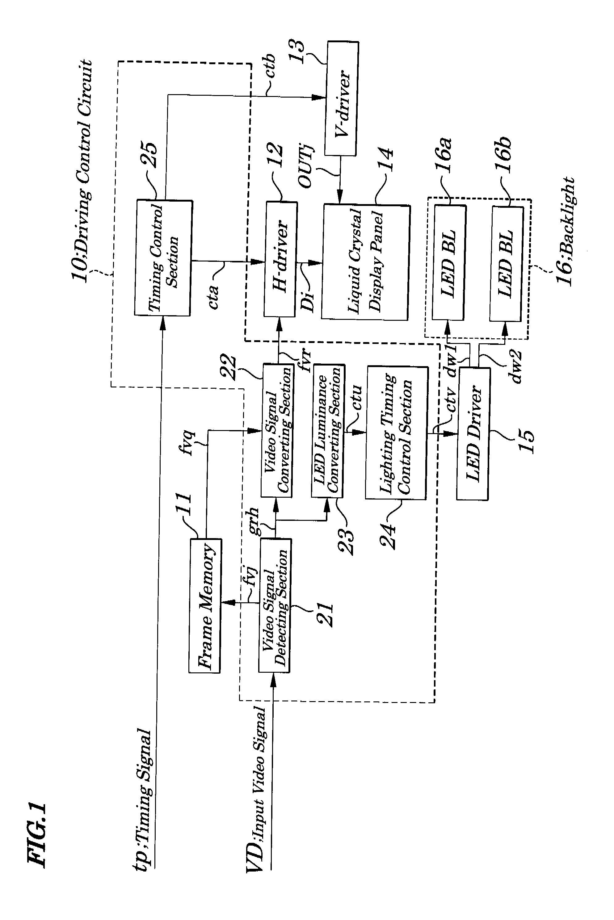
[0069]FIG. 1 is a block diagram showing electrical configurations of main components of a liquid crystal display device according to a first embodiment of the present invention. The liquid crystal display device of the first embodiment, as shown in FIG. 1, includes a driving control circuit 10, a frame memory 11, an H-driver 12, a V-driver 13, a liquid crystal display panel 14, an LED driver 15, and a backlight 16. The driving control circuit 10 has a video signal detecting section 21, a video signal converting section 22, an LED luminance converting section 23, a lighting timing control section 24, and a timing control section 25. The driving control circuit 10 is integrated into, for example, one IC (Integrated Circuit).

[0070]The video signal detecting section 21 detects, in a manner to correspond to each of LED blocks (LED BL) 16a and 16b, the brightest gray level for each of the R, G, and B of an input video signal VD, in every frame period, and sends out the det...

Example

Second Embodiment

[0085]FIG. 7 is a block diagram showing electrical configurations of main components of a liquid crystal display device of a second embodiment of the present invention. In FIG. 7, same reference numbers are assigned to components having the same functions as in the first embodiment in FIG. 1. In the liquid crystal display device of the second embodiment, as shown in FIG. 7, instead of the driving control circuit 10 shown in FIG. 1, a driving control circuit 10A having different configurations is provided newly. In the driving control circuit 10A, instead of the video signal detecting section 21A shown in FIG. 1, a video signal detecting section 21A having different configurations is provided newly. The video signal detecting section 21 detects, in a manner to correspond to each of LED blocks 16a and 16b, an average value of gray levels within a specified range including the brightest gray level for each red (R), green (G), and blue (B) of the input video signal VD i...

Example

Third Embodiment

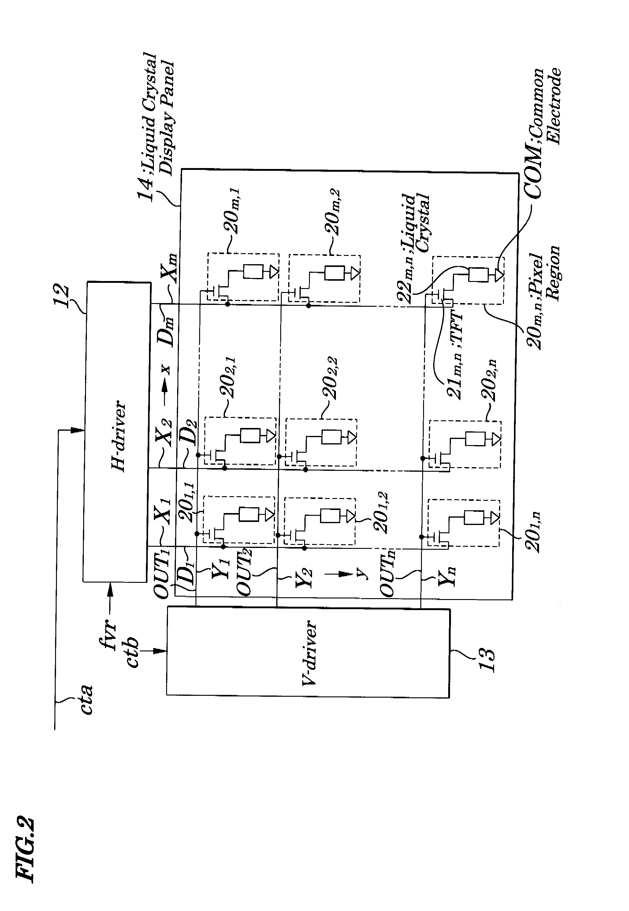
[0087]FIG. 8 is a block diagram showing electrical configurations of main components of a liquid crystal display device according to a third embodiment of the present invention. In FIG. 8, same reference numbers are assigned to components having the same functions as in the first embodiment in FIG. 2. In the liquid crystal display device of the third embodiment, as shown in FIG. 8, instead of the driving control circuit 10A, a driving control circuit 10B having different configurations and a frame memory 27 are newly provided. An overdriving section 26 is additionally mounted in the driving control circuit 10B. The frame memory 27 stores a converting video signal “fvr” fed from the video signal converting section 22 for every frame and sends out the stored video signal as a converting video signal “fvqa” to the overdriving section 26. The overdriving section 26 converts, in synchronization with output timing of the converted video signal “fvr” output from the video s...


PUM


Abstract

A liquid crystal display device capable of improving quality of moving images is provided. Each LED (Light Emitting Diode) block is turned ON according to a response of a liquid crystal corresponding to a light emitting region and the brightest gray level is detected for each of red (R), green (G) and blue (B) of an input video signal in every frame period and an input video signal is converted into a value obtained by being multiplied by an upper limit gray level and then by being divided by the brightest gray level and a gray level voltage corresponding to the converted value is applied to each data electrode and, during a lighting period of LED blocks, each LED block is made to flash at a duty corresponding to a rate of the brightest gray level to the upper limit gray level.

Description

INCORPORATION BY REFERENCE[0001]This application is based upon and claims the benefit of priority from Japanese Patent Application No. 2006-189352, filed on Jul. 10, 2006, the disclosure of which is incorporated herein in its entirely by reference.BACKGROUND OF THE INVENTION[0002]1. Field of the Invention[0003]The present invention relates to a liquid crystal display device, driving control circuit and driving method used in the same display device, and more particularly to the liquid crystal display device having an LED (Light Emitting Diode) backlight and suitably used when a moving image is displayed, the driving control circuit and the driving method used in the same display device.[0004]2. Description of the Related Art[0005]To display a television image, a CRT (Cathode Ray Tube) has been conventionally used, however, in recent years, liquid crystal display devices are widely used. In each of the liquid crystal display devices, a liquid crystal display panel is a non-luminous p...

Claims


Application Information

Patent Timeline
IPC IPC(8): G09G3/36
CPCG09G3/3406G09G2320/0646G09G2310/0245G09G3/3648
Inventor HONBO, NOBUAKI
Owner NEC LCD TECH CORP
Why Eureka
Try Eureka