Magnetic disk device

Inactive Publication Date: 2008-01-31
TOSHIBA STORAGE DEVICE CORP
View PDF3 Cites 11 Cited by
  • Summary
  • Abstract
  • Description
  • Claims
  • Application Information

AI Technical Summary

Benefits of technology

[0009]According to the present invention, the weight imbalance is eliminated by fastening a disk clamp with screws having such weights that generate torque in the opposite direction to the

Problems solved by technology

However, a slight gap exists between the hub of the spindle motor and the magnetic disks.
After the magnetic disks have been fixed, therefore, weight imba

Method used


Image

  • Magnetic disk device
  • Magnetic disk device
  • Magnetic disk device

Examples


Embodiment Construction

[0022]An embodiment of the present invention will be described below with reference to the drawings.

[0023]Structure of a Hard Disk Drive:

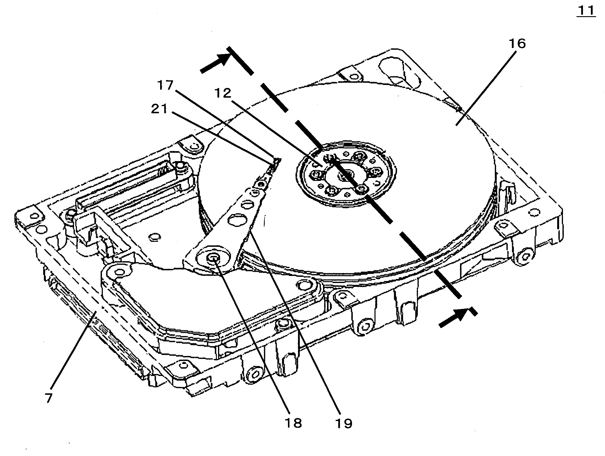
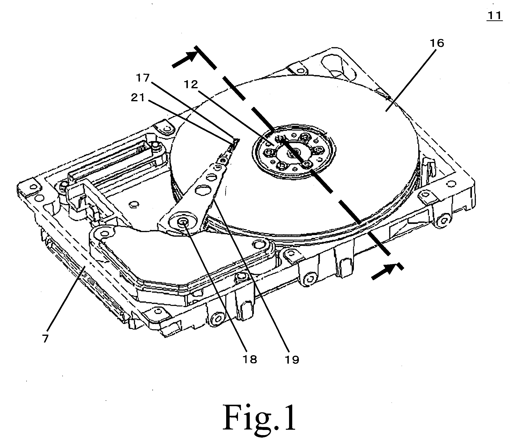
[0024]FIG. 1 schematically illustrates the internal structure of a specific example of a sealed recording disk drive, i.e., a hard disk drive (HDD) 11. The HDD 11 includes a box-shaped chassis body 7 for defining the internal space of a flat rectangular parallelepiped, for example. The housing space houses at least one magnetic disk 16 which serves as a recording medium. The magnetic disk 16 is mounted on a spindle motor 12. The spindle motor 12 can be rotated at a high speed, such as 7200 rpm, 10000 rpm, or 15000 rpm, for example.

[0025]The housing space further houses an actuator arm 19. The actuator arm 19 is provided for each of the front surface and the rear surface of the magnetic disk 16. The actuator arm 19 is attached with a head suspension 21 at the leading end thereof. The head suspension 21 extends forward from the leading end of the act...


PUM


Abstract

The present invention provides a magnetic disk device which uses a plurality of screws of different weights for fastening a disk clamp, and which combines the screws of different weights in such a manner to eliminate weight imbalance. Accordingly, the device does not use extra components such as a weight for eliminating the weight imbalance, and thus achieves cost reduction.

Description

BACKGROUND OF THE INVENTION[0001]1. Field of the Invention[0002]The present invention relates to a magnetic disk device used as an external storage device of a computer system.[0003]2. Description of the Related Art[0004]A magnetic disk device is not only used as an auxiliary storage device of a computer but also mounted on a mobile terminal device, a video device, and so forth. With such expansion of the range of applications, further increase in capacity and improvement in response of the magnetic disk device have been sought. To increase the capacity, the number of disks mounted on the magnetic disk device has been increasing. Further, to improve the response, the rotation speed of a spindle motor has been increasing.[0005]A plurality of the magnetic disks are stacked through a hub fixed to the shaft of the spindle motor, and a disk clamp is screwed to fix the disks. However, a slight gap exists between the hub of the spindle motor and the magnetic disks. Further, each of the mag...

Claims


Application Information

Patent Timeline
IPC IPC(8): G11B21/02
CPCG11B19/2027
Inventor SHIKANO, KAZUNORI
Owner TOSHIBA STORAGE DEVICE CORP
Why Eureka
Try Eureka