Lamp supporting device and backlight device

Inactive Publication Date: 2008-02-14
SHARP KK
View PDF3 Cites 3 Cited by
  • Summary
  • Abstract
  • Description
  • Claims
  • Application Information

AI Technical Summary

Problems solved by technology

However, in a case of the description (1), there is a problem that it is impossible to hold two or more of lamps at once, thus increasing the number of the second lamp holding members relative to the number of all lamps and assembling workability of the lamp holding members is thereby deteriorated.
In addition, in a case of the description (2), there is a problem that a forming mold is required for each of the plurality of kinds of the first lamp holding members corres

Method used


Image

  • Lamp supporting device and backlight device
  • Lamp supporting device and backlight device
  • Lamp supporting device and backlight device

Examples


embodiment 1

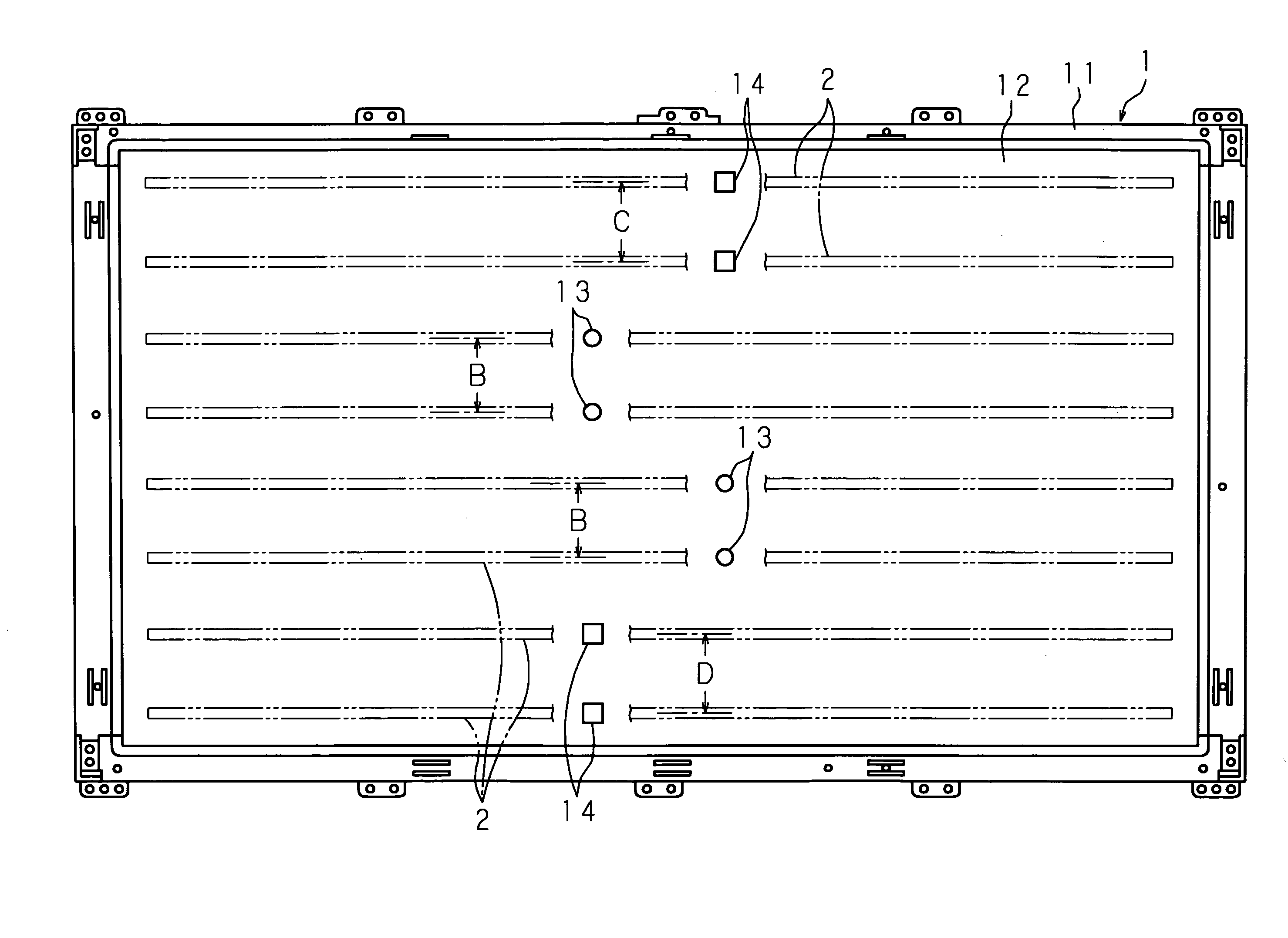
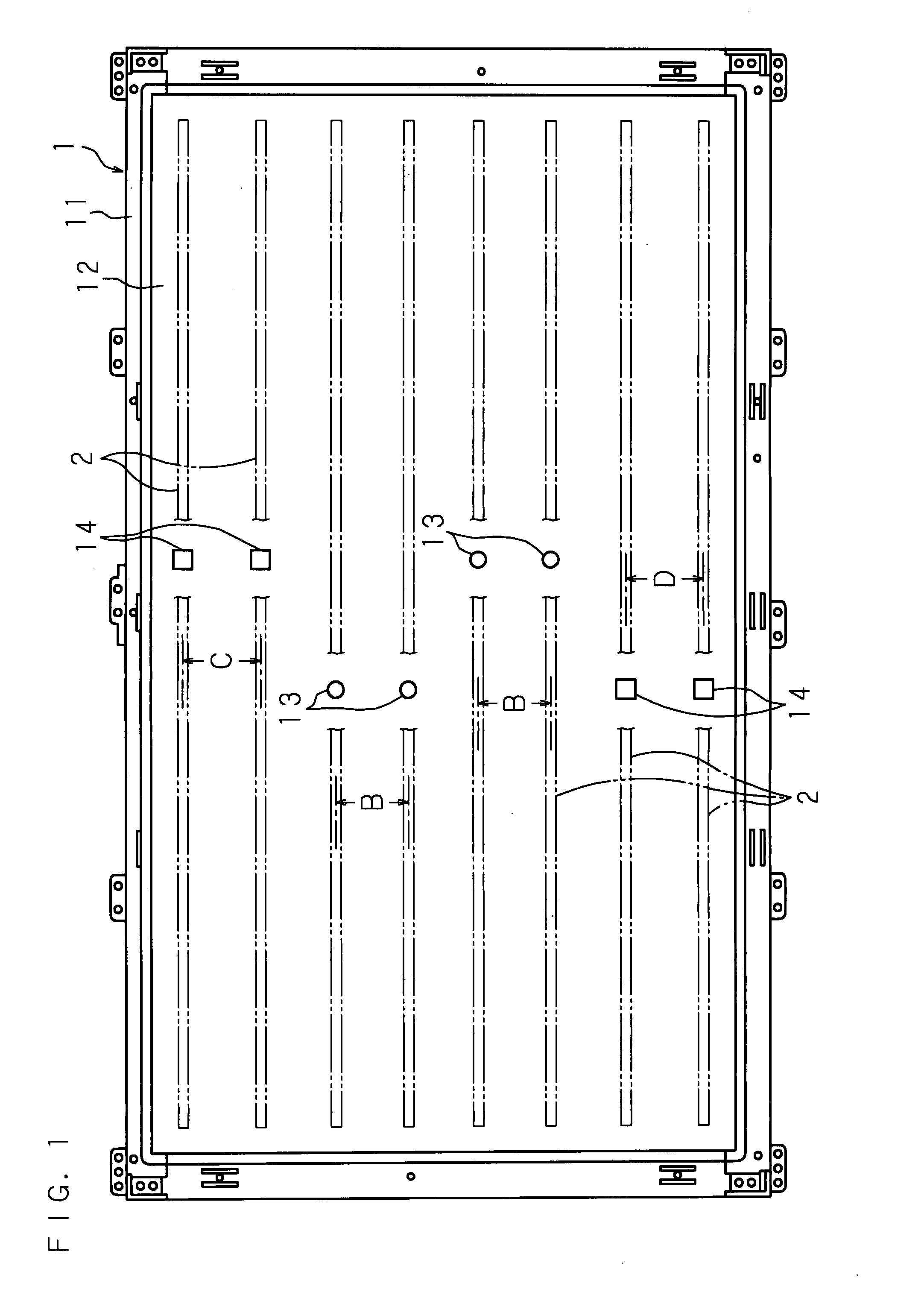
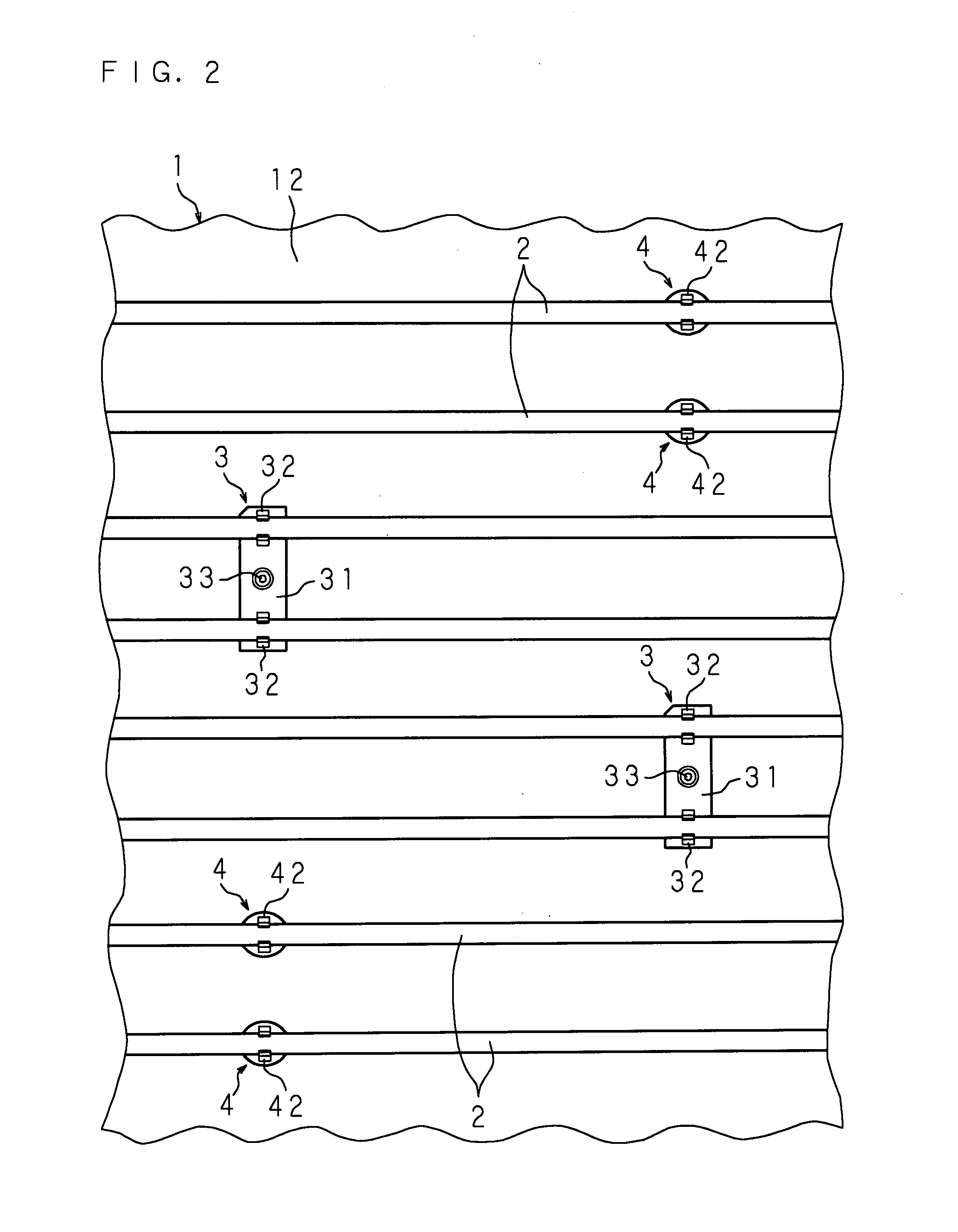
[0074]FIG. 1 is a front view showing a structure of a backlight device provided with a lamp supporting device, FIG. 2 is a front view of an expanded essential part, FIG. 3 is a schematic view showing a relation between a lamp holding member and a mounting hole, FIG. 4 is an expanded sectional view of a mounting part of the first lamp holding member, and FIG. 5 is an expanded sectional view of a mounting part of the second lamp holding member.

[0075]The backlight device of Embodiment 1 comprises a housing member 1 in a box shape, with front side opened, having a frame part 11 in a rectangular solid shape and a rear wall 12, with a peripheral part connected to the frame part 11 to close a rear side end of the frame part 11; a plurality of lamps 2 in a cylindrical shape juxtaposed at a vertically different interval in the housing member 1; an end part holder for holding both end parts of the lamps 2 in the inside of the frame part 11; a plurality of the first lamp holding members 3 for ...

embodiment 2

[0085]FIG. 9 is a front view showing other structure of the backlight device provided with the lamp supporting device, FIG. 10 is a front view of an expanded essential part, and FIG. 11 is a schematic view showing a relation between the lamp holding members and the mounting holes. In this backlight device, instead of differentiating the shapes of the first mounting holes 13 and the second mounting holes 14 as the identifying means for identifying the positions to which the first and second lamp holding members 3 and 4 are mounted, the first mounting holes 13 are opened two by two in the juxtaposed direction of the lamps 2, and the second mounting holes 14 vertically adjacent to the first mounting holes 13 are opened at the positions separate from the first mounting holes 13 along the length direction of the lamps 2, and further the second mounting holes 14 are opened, which are adjacent to each other in the juxtaposed direction, at the separate positions along the length direction o...


PUM


Abstract

A lamp supporting device for supporting a plurality of lamps so as to be juxtaposed includes the first and second mounting holes for mounting the first lamp holding member having a plurality of holding parts for holding middle parts of the lamps and the second lamp holding member having a holding part of the number different from that of the holding parts of the first lamp holding member; and identifying means for identifying positions to which the first and second lamp holding members are mounted.

Description

CROSS-REFERENCE TO RELATED APPLICATIONS[0001]This Nonprovisional application claims priority under 35 U.S.C.§119(a) on Patent Application No. 2006-216167 filed in Japan on Aug. 8, 2006 and Patent Application No. 2007-176385 filed in Japan on Jul. 4, 2007, the entire contents of which are hereby incorporated by reference.BACKGROUND[0002]1. Technical Field[0003]The present invention relates to a lamp supporting device for supporting a plurality of lamps so as to be juxtaposed and a backlight device provided with the lamp supporting device.[0004]2. Description of Related Art[0005]A display device such as a television has a backlight device disposed at a rear side of a display section having a display surface for displaying an image on the front side, and the backlight device is provided with a lamp supporting device for supporting a plurality of lamps so as to be juxtaposed.[0006]The backlight device includes a housing member with front side opened; a plurality of lamps juxtaposed vert...

Claims


Application Information

Patent Timeline
IPC IPC(8): F21V21/00
CPCF21V19/009G02F1/133608G02F1/133604
Inventor SHIMIZU, MASAKITSUJI, TSUTOMUKIKUCHI, TAKAHARU
Owner SHARP KK
Why Eureka
Try Eureka