

Lens unit and image reading apparatus using the same
a technology of image reading and lens unit, applied in the direction of mountings, optics, instruments, etc., can solve the problems of decentering error, deterioration of imaging performance, and performance on the ccd surface can still be held well, and achieve the effect of simple structur
- Summary
- Abstract
- Description
- Claims
- Application Information
AI Technical Summary
Benefits of technology
Problems solved by technology
Method used
Image

Examples
embodiment 1
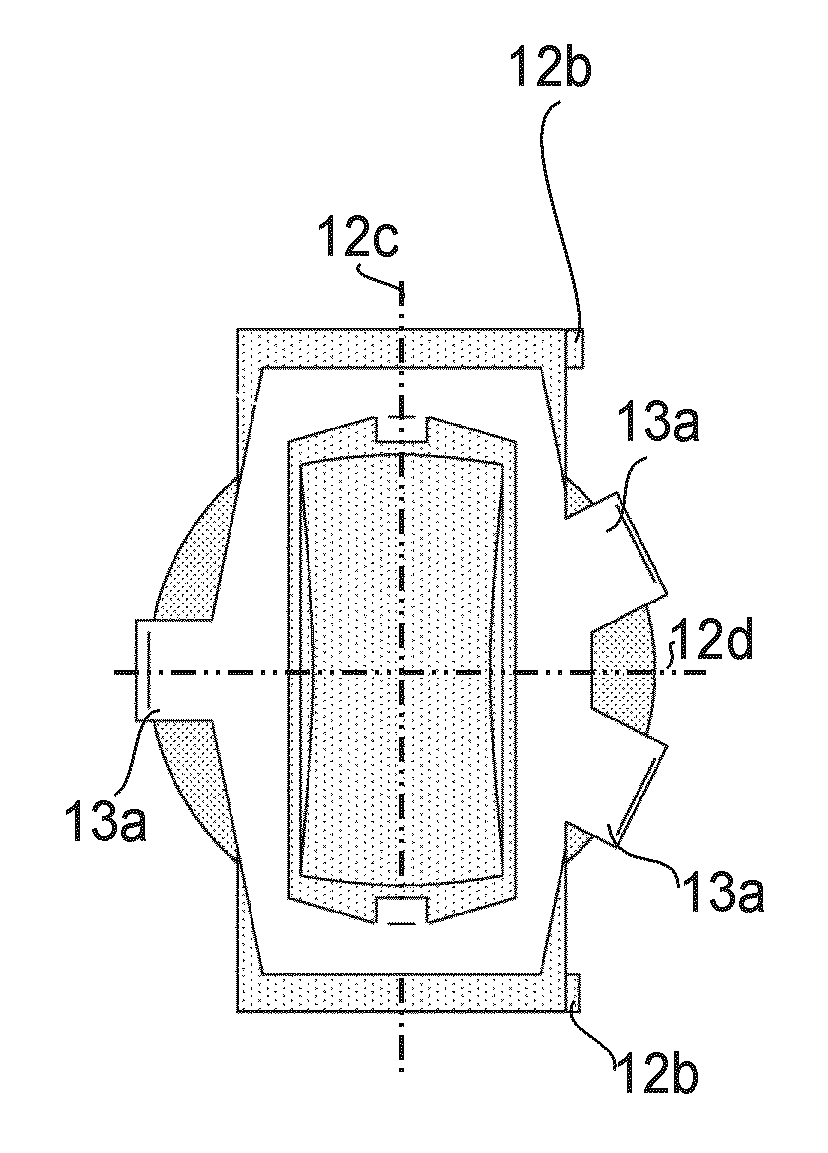
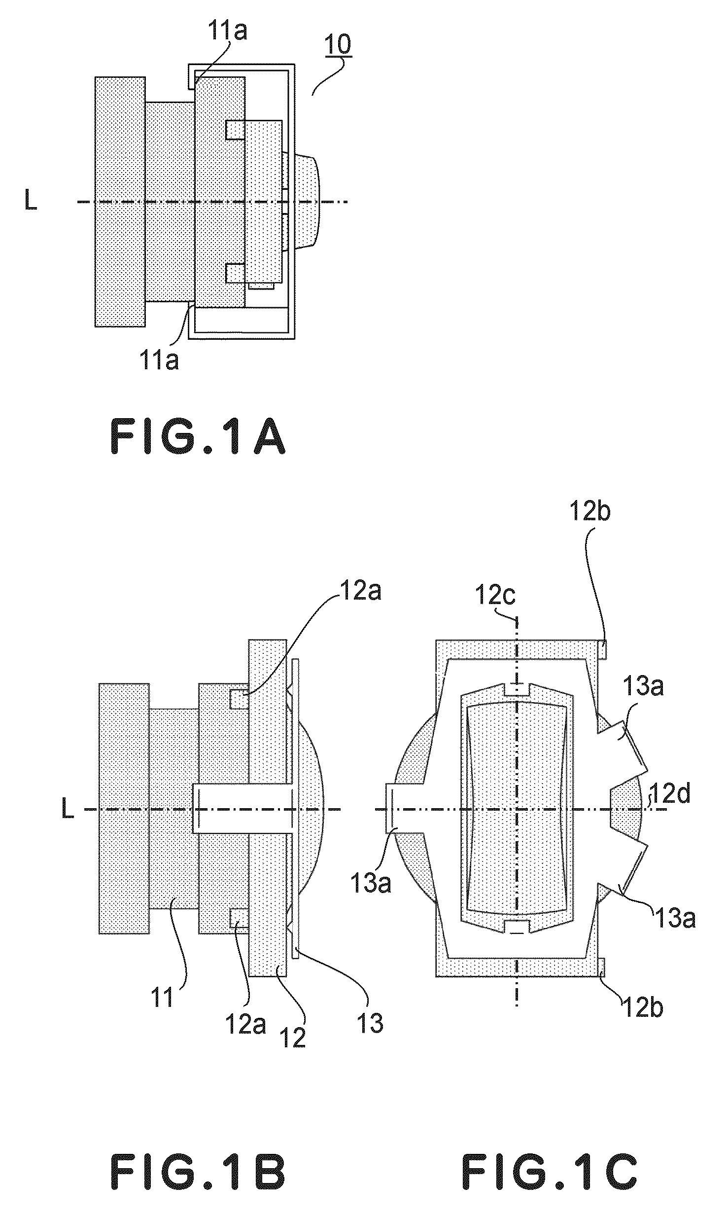
[0052]FIG. 1A-FIG. 1C are trihedral diagrams showing a lens unit according to a first embodiment of the present invention. FIG. 1A is a top plan view, FIG. 1B is a side view, and FIG. 1C is a front elevation.
[0053]Denoted in FIG. 1A-FIG. 1C at 10 is a lens unit (imaging lens) to be used in an image reading apparatus wherein imagewise information of an original is imaged on a photoelectric conversion element and is read sequentially. Denoted at 11 is a barrel member (lens barrel) having a cylindrical shape at the outer periphery thereof. It serves to hold at least one rotationally symmetric lens having a rotationally symmetric shape with respect to the optical axis L.
[0054]Denoted at 12 is an anamorphic lens, at least one surface of which is defined by an anamorphic surface. The anamorphic lens is held by the barrel 11, while circumscribing one end portion of the barrel. The anamorphic lens 12 of the present embodiment has an outer configuration of rectangular shape. Here, of the dim...
embodiment 2
[0080]FIG. 3A, FIG. 3B and FIG. 3C are trihedral diagrams illustrating a lens unit according to a second embodiment of the present invention. In FIG. 3A-FIG. 3C, like numerals are assigned to similar components corresponding to those of FIG. 1.
[0081]The present embodiment differs from the first embodiment described hereinbefore in that the number of legs 23a of the elastic member 23 is two in the present embodiment. Other structures and the optical function are similar to the first embodiment, and similar advantageous effects are obtained likewise in the present embodiment.
[0082]Denoted in the drawings at 23 is an elastic member which functions to push the anamorphic lens 12 against the barrel member 11 along the optical axis direction. Denoted at 23a are legs (branches) of the elastic member 33 which are configured to be hooked at the groove 11a formed in the outer peripheral portion of the barrel member 11. The elastic member 23 has two legs 23a.
[0083]In the present embodiment, o...
embodiment 3
[0089]FIG. 4A, FIG. 4B and FIG. 4C are trihedral diagrams illustrating a lens unit according to a third embodiment of the present invention. In FIG. 4A-FIG. 4C, like numerals are assigned to similar components corresponding to those of FIG. 1.
[0090]The present embodiment differs from the abovementioned second embodiment in that three pins 32a are used as the coaxiality maintaining means in the present embodiment. Other structures and the optical function are similar to second embodiment, and similar advantageous effects are obtained likewise.
[0091]Denoted in the drawings at 32a are pins as the coaxiality maintaining means which function to engage the anamorphic lens 12 and the barrel member 11 with each other and to align their central axes with each other. Further, it functions to allow relatively rotation of the lens and the barrel relative to each other, for rotary adjustment with reference to their central axes aligned. The present embodiment uses three pins 32a.
[0092]Denoted i...
PUM
 Abstract
Description
Claims
Application Information