Filter Cleaning Head

a filter head and filter cleaning technology, applied in gravity filters, loose filtering materials, stationary filtering elements, etc., can solve the problem of easy clogging of the inlet surface by suspended particles, and achieve the effect of reducing the width and reducing the force acting

Inactive Publication Date: 2008-02-28
ARKAL FILTRATION SYST C S
View PDF4 Cites 33 Cited by
  • Summary
  • Abstract
  • Description
  • Claims
  • Application Information

AI Technical Summary

Benefits of technology

[0016] The usage of a nozzle that both has a compact orifice and is biased towards the filter element surface allows optimization of the suction process. The compact orifice concentrates the available pressure differential on a small area for effective suction, while the biased nozzle maintains permanent contact with the filter element surface preventing parasite side flow. The biasing force is selected so that the contact friction and wear are limited. The orifice rim may be made with reduced width, further reducing the forces acting between the rim and the filter element. The inventive nozzle allows operation with cleaning pressure differential much higher than the pressure differential, achievable with prior art nozzles.

Problems solved by technology

The inlet is in fluid communication with an inlet chamber bounded by an inlet surface of the filter element and the inlet surface is prone to clogging by suspended particles, e.g. waste, carried with the incoming raw fluid.

Method used


Image

  • Filter Cleaning Head
  • Filter Cleaning Head
  • Filter Cleaning Head

Examples


Embodiment Construction

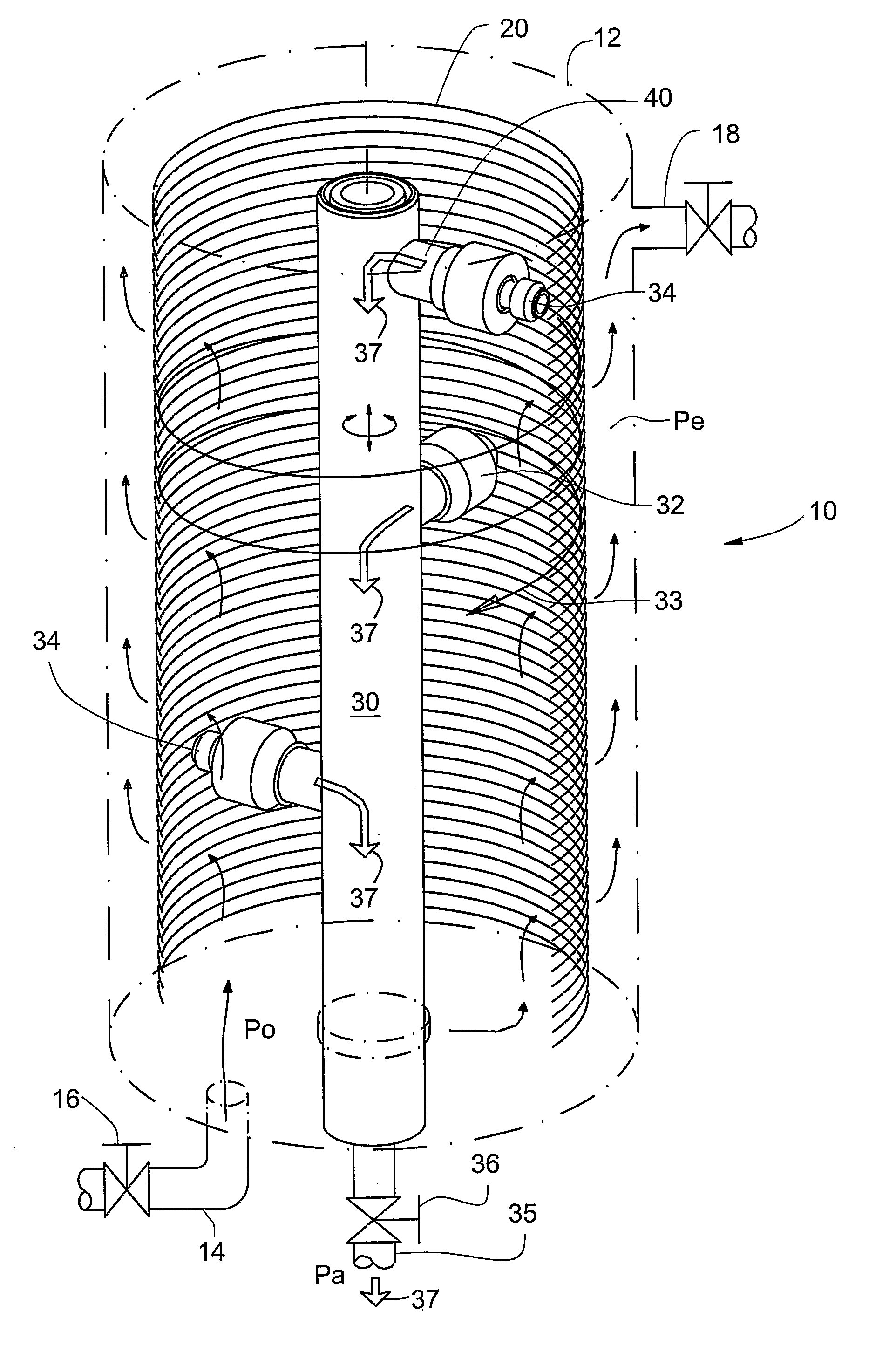
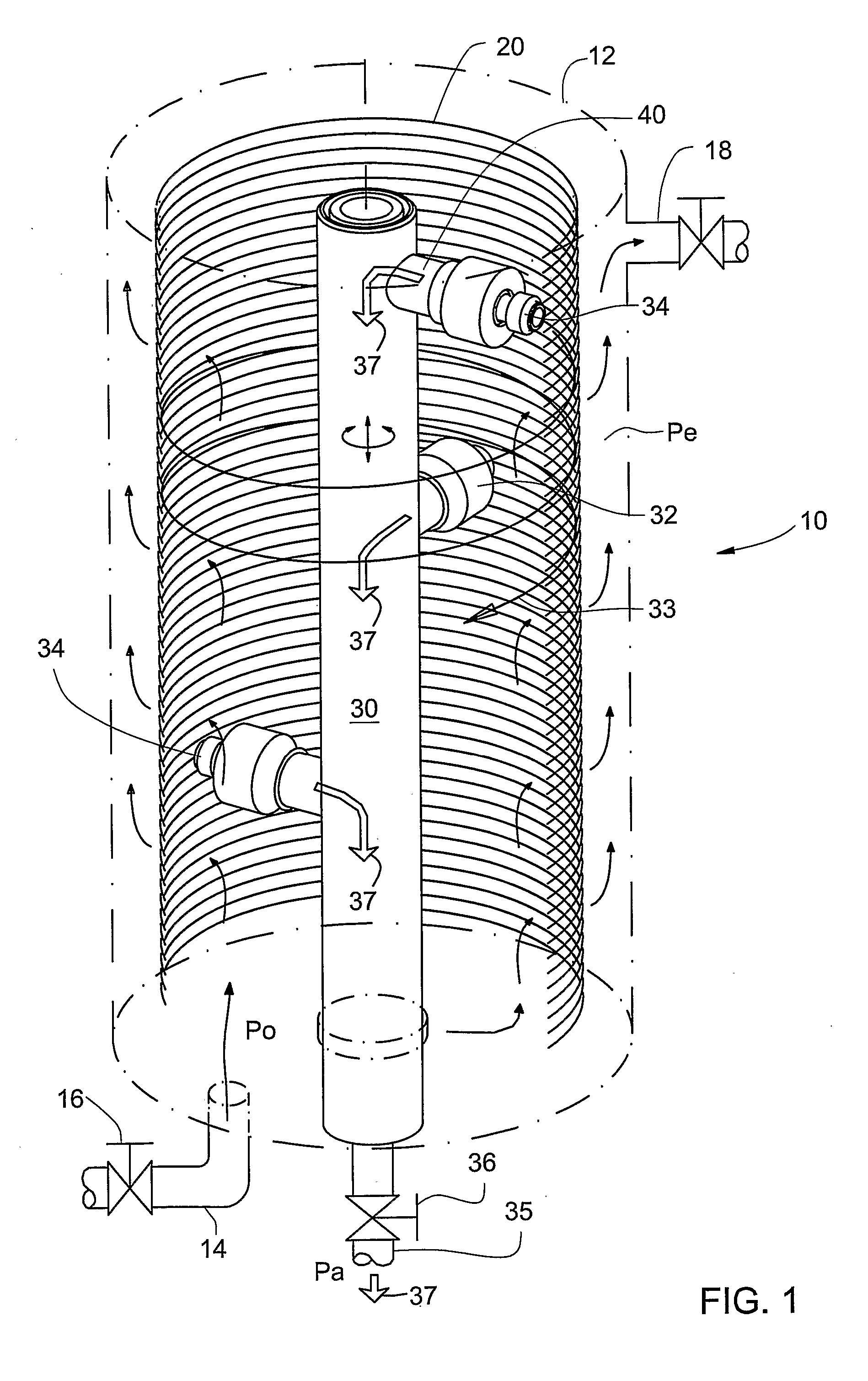
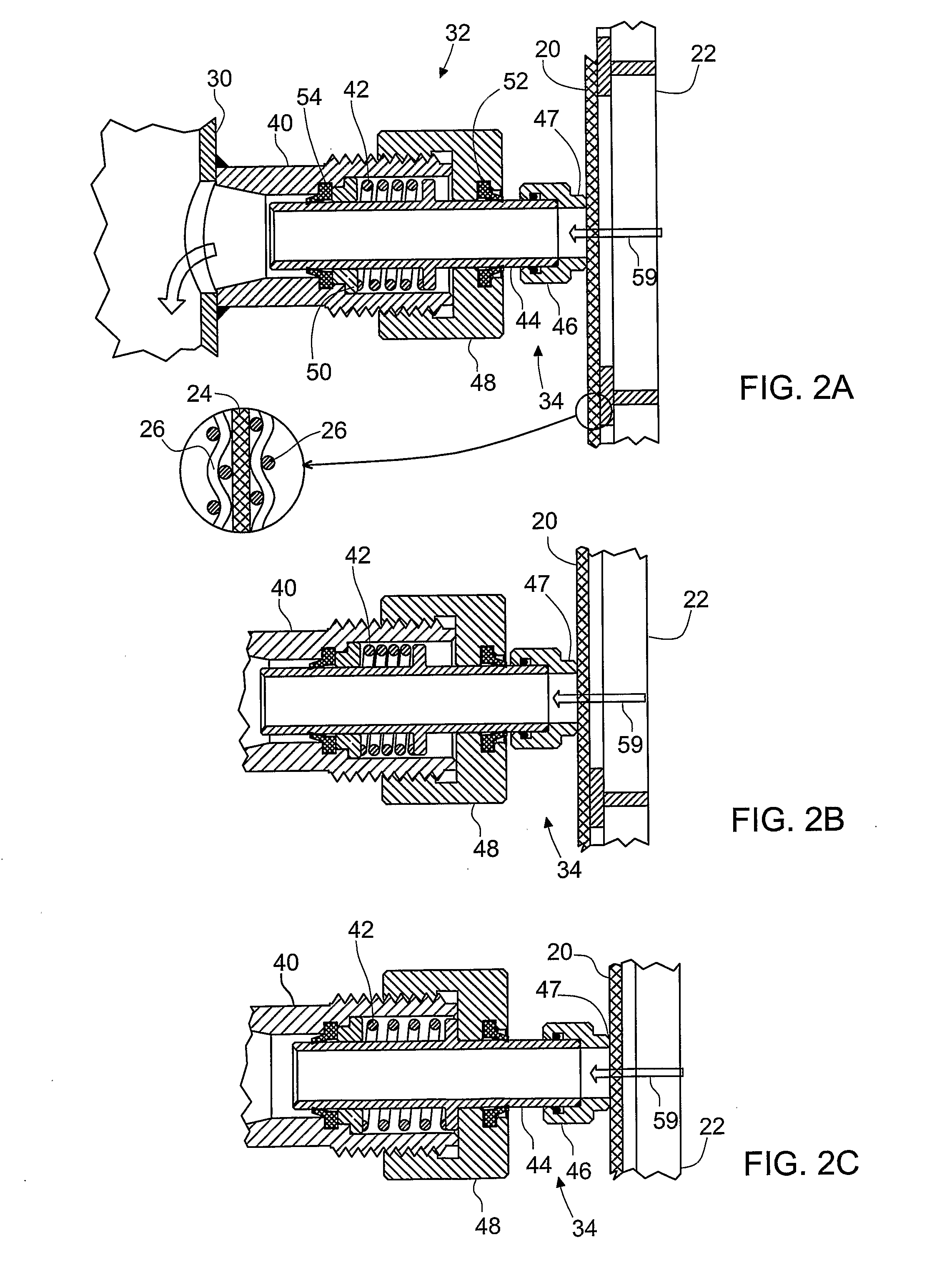
[0028] With reference to FIG. 1, there is shown schematically a filter 10, e.g. for filtering irrigation water, comprising a housing 12 with an inlet port 14, an inlet stop valve 16, an outlet port 18, and a filtering element, e.g. mesh 20. The mesh 20 has the form of a straight circular cylinder and is supported from the outer side by a carrying skeletal structure 22 (shown in FIGS. 2A-2C). The mesh 20 may comprise layers of a fine soft mesh 24 supported from one or both sides by a rigid and coarser grid 26.

[0029] A rotary pipe 30 with radial cleaning heads 32, each head having a carrying basis 40 and a movable nozzle 34, is mounted coaxially with the filter mesh 20. The pipe 30 is supported in the housing 12 also for axial translation so that a driving system (not shown) can both rotate and translate the pipe. By virtue of the rotation and translation movement, the cleaning heads 32 can scan the inlet (internal) surface of the mesh 20 along a helical line 33, parallel to the inle...


PUM

PropertyMeasurementUnit
pressureaaaaaaaaaa
pressureaaaaaaaaaa
operative pressureaaaaaaaaaa

Abstract

A filtering device has a filter element disposed between the inlet and the outlet of the device. The inlet surface of the filter element is prone to clogging by suspended particles, e.g. waste, carried with the incoming raw fluid. The invention provides a cleaning head for the filtering device, comprising a basis and a nozzle movably mounted thereon. The cleaning head basis is mounted on a driving mechanism so that the nozzle can scan the inlet surface parallel thereto, and can clean the inlet surface by means of a backwash flow passing through the filter element into the nozzle under a cleaning pressure differential created by connecting the nozzle to a low-pressure outlet. The nozzle maintains, during scanning, permanent contact with the inlet surface so that lateral flow directly into the nozzle is essentially prevented despite variations of distance between the cleaning head basis and the inlet surface during the scanning.

Description

FIELD OF THE INVENTION [0001] This invention relates to self-cleaning and manually cleaned filters, in particular to filters using a suction head to clean clogged surface of a filter element. BACKGROUND OF THE INVENTION [0002] GB 1485989 discloses a filter with an outward-flow cylindrical filter element which is cleaned by three axially and angularly spaced rotary nozzles. The nozzles are axially elongated and spring-loaded into contact with the inner surface of the filter element. They are connected by a central duct to a solids discharge valve, which opens to atmosphere so that the pressure outside the element causes reverse flow through the filter element opposite the nozzles. The duct is rotated by a motor so that the three nozzles sweep axially overlapping sections of the filter element. Nozzles are spring-loaded at each axial end or in their middle and are movable in radial direction. Each nozzle comprises a cloth-reinforced phenolic resin pad which engages the internal wall o...

Claims


Application Information

Patent Timeline
Patent Type & Authority Applications(United States)
IPC IPC(8): B01D29/23B01D29/68
CPCB01D29/23B01D2201/082B08B5/04B01D29/686B01D29/688B01D29/68
Inventor SHIEKELMACHER, RUBEN
Owner ARKAL FILTRATION SYST C S
Why Eureka
Try Eureka