Bicycle illumination apparatus

a technology of illumination apparatus and bicycle, which is applied in the direction of cycle equipment, lighting support devices, instruments, etc., can solve the problems of insufficient output, low output rate, and inability to achieve sufficient voltage at low traveling speed at which low voltage is generated, so as to reduce the number of illuminated light sources, the effect of reducing the needless power consumption

Inactive Publication Date: 2008-05-01
SHIMANO INC
View PDF7 Cites 14 Cited by
  • Summary
  • Abstract
  • Description
  • Claims
  • Application Information

AI Technical Summary

Benefits of technology

[0017]The bicycle illumination apparatus according to a sixth aspect is the apparatus according to the fifth aspect, wherein the controller is further configured to control the switches so that the light sources turn on one by one in sequence in accordance with the increase in the rotational speed detected by the rotating state detector. In this case, since the lit light sources increase in number one by one as the speed increases, needless power consumption can be reduced.
[0018]According to the present invention, since the connection with the light sources is selectively controlled according to the rotating state of the power generator, the number of illuminated light sources can be increased or reduced according to the rotating state. Therefore, the optimum output is obtained according to the rotating state of the power generator.

Problems solved by technology

In the case of only one light-emitting diode, a certain output is obtained at a low rotational speed, but when the rotational speed increases, problems are encountered in that the rate of increase in output lowers and reaches a substantial plateau.
Therefore, problems are encountered in that output is insufficient when the bicycle is ridden at high speeds.
Therefore, when a generator in which multiple light-emitting diodes are connected in series is operated, sufficient voltage might not be obtainable at low traveling speeds at which the low voltage is generated.

Method used


Image

  • Bicycle illumination apparatus
  • Bicycle illumination apparatus
  • Bicycle illumination apparatus

Examples


second embodiments

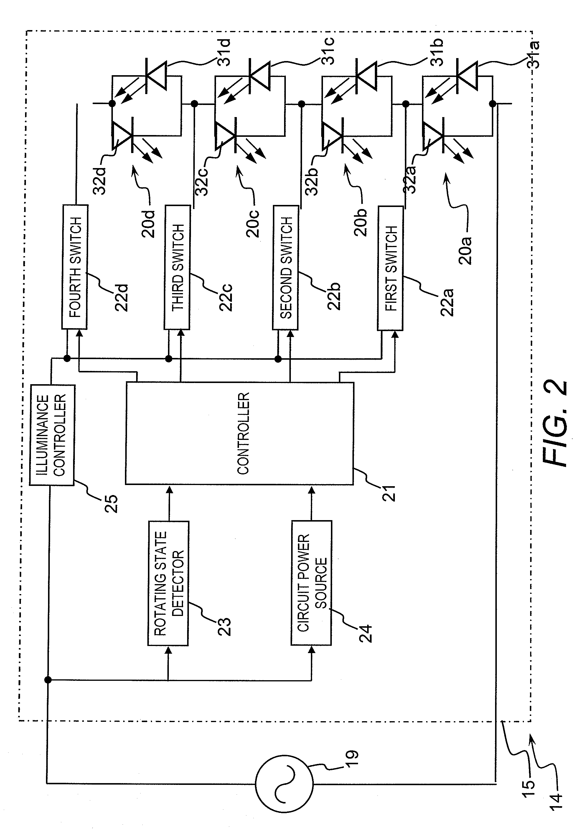
[0046]In the first embodiment, two light-emitting diodes connected in parallel were connected in parallel so that the light sources 20a to 20d had different polarities, and the light sources 20a to 20d were lit using the unaltered AC output of power generation unit 19. However, in the second embodiment, the headlight 114 is provided with a rectifier circuit 126 for rectifying AC power to a direct current, as shown in FIG. 6.

[0047]The rectifier circuit 126 is disposed between the illuminance controller 25 and one end of power generation unit 19. The rectifier circuit 126 is configured from a full-wave rectifier circuit that forms a bridge connection between the four diodes. A circuit power source 124 does not have a rectifying function, but has a constant-voltage function for converting direct current to a specific voltage.

[0048]Light sources 120a to 120d are connected in series with each of the light sources 120a to 120d having a single light-emitting diode 131a to 131d, respectivel...


PUM


Abstract

A bicycle illumination apparatus is provided with a plurality of light sources and a controller. The light sources include at least one light-emitting diode that emits light in accordance with an electrical output of a generator. The controller is configured to selectively control an electrical connection between the power generator and the light sources in accordance with a rotating state of the generator.

Description

CROSS-REFERENCE TO RELATED APPLICATIONS[0001]This application claims priority under 35 U.S.C. §119 to Japanese Patent Application No. 2006-293922, filed Oct. 30, 2006. The entire disclosure of Japanese Patent Application No. 2006-293922 is hereby incorporated herein by reference.BACKGROUND OF THE INVENTION[0002]1. Field of the Invention[0003]This invention generally relates to an illumination apparatus. More specifically, the present invention relates to a bicycle illumination apparatus capable of being connected to a power generator that generates electricity in accordance with the movement of the bicycle.[0004]2. Background Information[0005]Bicycling is becoming an increasingly more popular form of recreation as well as a means of transportation. Moreover, bicycling has become a very popular competitive sport for both amateurs and professionals. Whether the bicycle is used for recreation, transportation or competition, the bicycle industry is constantly improving the various compo...

Claims


Application Information

Patent Timeline
Patent Type & Authority Applications(United States)
IPC IPC(8): F21L13/06B62J6/16
CPCB62J6/001B62J6/01
Inventor KITAMURA, SATOSHI
Owner SHIMANO INC
Why Eureka
Try Eureka