Relay server and relay communication system

a relay communication and relay technology, applied in the field of relay communication system, can solve the problems of not easy to construct an expansible and flexible system, not easy to cause a user, and difficult to achieve the effect of reducing the load of the communication process, preventing the resource, and not causing the user

Active Publication Date: 2008-06-12
MURATA MASCH LTD
View PDF73 Cites 48 Cited by
  • Summary
  • Abstract
  • Description
  • Claims
  • Application Information

AI Technical Summary

Benefits of technology

[0013]An object of the invention is to provide a relay communication system which can be easily operated and which can allow terminals to share and operate a resource with a necessary opposite terminal even when the terminals are connected to different LANs and managed under different protocols. Another object of the invention is to provide a relay server used for the system. Still another object of the invention is to provide a dynamic relay communication system which has excellent expansibility and flexibility and which can cope with a variation of resources or a variation in access status of relay points due to movement or the like of the resources.
[0014]Still another object of the invention is to provide a relay server suitable for a dynamic relay communication system and which can be used without any consciousness, since it does not require troublesome works such as a change of set conditions even when a terminal having been registered move between LANs.
[0015]Still another object of the invention is to provide a relay server which can allow a user to select a resource handling method.
[0042]The operating conditions of the relay servers and the client terminals are periodically monitored and checked and the relevant information is always updated. Accordingly, even when a change due to the deletion of a resource, a change in access status due to a power ON / OFF state or a log ON / OFF state of the relay servers or the client terminals, or an unexpected trouble occurs, the states can be easily grasped, thereby not causing a user's confusion.
[0043]It is possible to use the resources without any consciousness, since it does not require troublesome works such as a change of set conditions even when a terminal having been registered in a LAN moves to a different LAN.
[0044]One mode of both the synchronous mode in which the seeming operation and the essential operation of the resource are synchronized with each other and the asynchronous mode in which they are not synchronized with each other can be selected at the time of operating the resource, depending on it. For example, when the synchronous mode is selected in which the operation details accompany the status of the resource, the client terminal T having copied a file can operate the file directly after the copy operation. As a result, it is not necessary to indirectly operate the file through a relay communication and thus it is possible to reduce a communication process load thereafter. On the other hand, when the asynchronous mode is selected, it is possible to prevent the resource from being repeatedly created and thus to efficiently use the storage unit in the relay communication system.

Problems solved by technology

However, such a type of system tends to be stiff because a network is virtually constructed.
Accordingly, it is not easy to construct an expansible and flexible system and the suggested systems have both merits and demerits in function, cost, and the like.
However, when a communication system includes plural LANs over a WAN, it is not possible to easily cope with such intention that resources such as folders are shared with plural terminals or files or that a file retained by a terminal is deleted by a different terminal.
The resources retained by the terminals vary endlessly due to deletion or movement thereof, but it is not easy to dynamically cope with such a variation.
The system may be downed for some reasons.
It is not also easy to dynamically cope with the variation in access status.

Method used


Image

  • Relay server and relay communication system
  • Relay server and relay communication system
  • Relay server and relay communication system

Examples


first embodiment

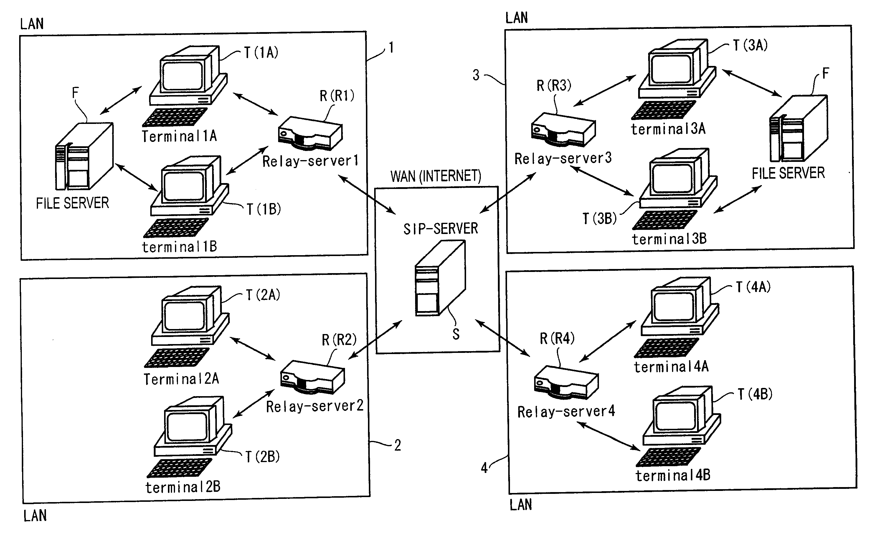
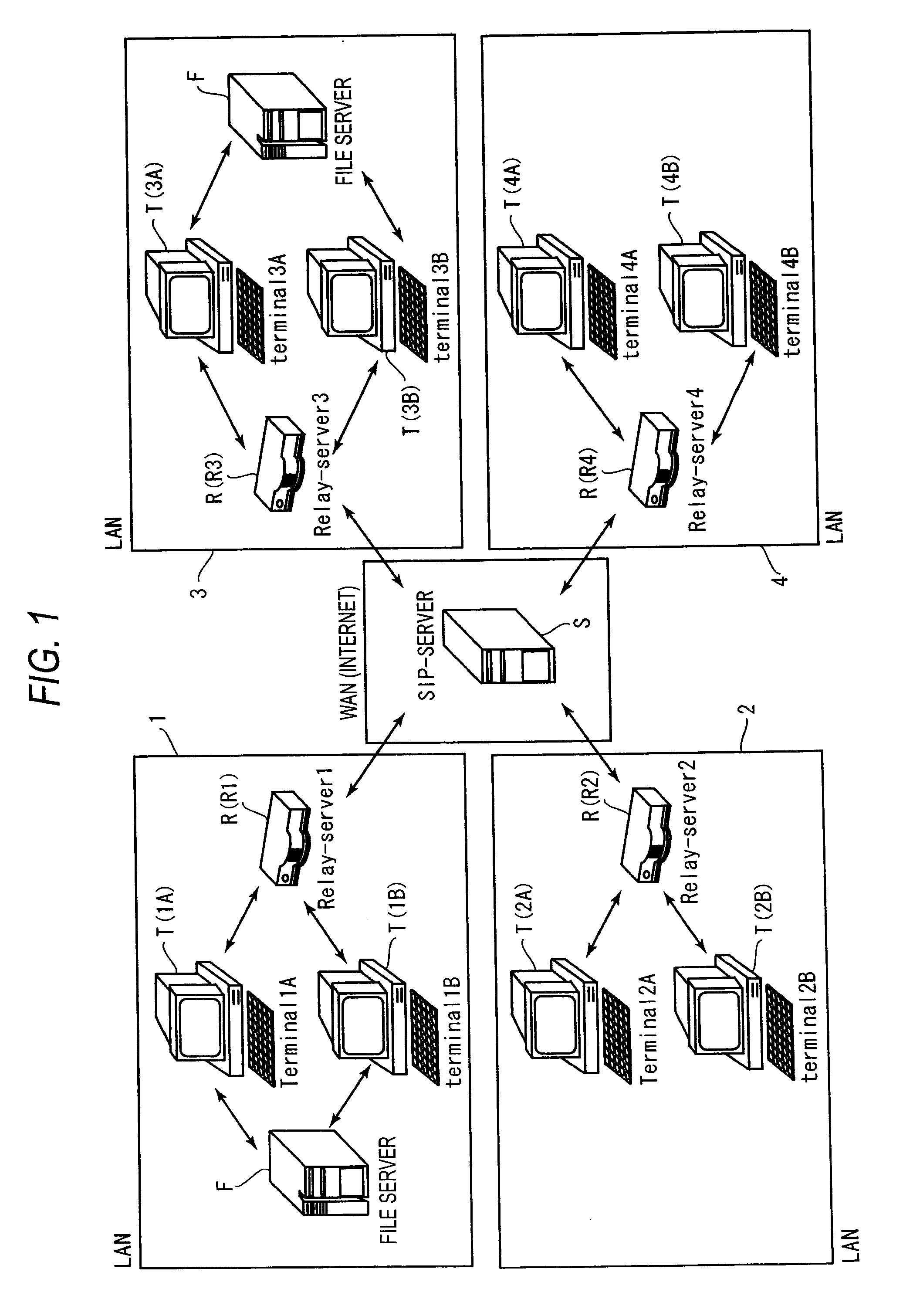
[0091]FIG. 1 illustrates an entire configuration of a relay communication system according to the invention. As shown in FIG. 1, the relay communication system includes a plurality of LANs connected to a WAN. The relay communication system includes an external server S, relay servers R, client terminals T, and file servers F. Although an example using the external server S will be exemplified, the relay servers R may directly communicate with each other without using the external server S.

[0092]In this embodiment, a system using a session initiation protocol (SIP) as a communication protocol between the external server S and the relay servers R in the WAN and between the relay server R and the client terminals T in the respective LANs is exemplified. However, protocols other than the SIP may be used as a communication protocol between the servers and the terminals.

[0093]The WAN (Wide Area Network) is a network for connecting different LANs. In this embodiment, the Internet is exempl...

second embodiment

[0188]A second embodiment of the invention provides a relay communication system which can dynamically cope with an unexpected trouble or a case where an access status of a relay server R or a client terminal T varies.

[0189]Elements of a relay communication system such as relay servers R and client terminals T and basic configurations of communication processes are equal to those of the first embodiment. This embodiment will be described in detail with reference to the flowchart of FIG. 20 and the sequence diagram of FIG. 21

[0190]FIG. 20 shows operation checking processes which are performed by the relay servers R. FIG. 21 shows a communication flow processed in the relay communication system at the time of performing the operation checking processes. In FIG. 21, the relay server R1 checks operations of the relevant relay servers R and an access trouble occurs in the relay server R3. In addition, in FIG. 21, the relay server R1 and the relay server R2 check operations of the client ...

third embodiment

[0222]A third embodiment of the invention provides a more dynamic relay communication system which can use the resources without any consciousness, since it does not require troublesome works such as a change of set conditions even when a client terminal T having been registered in a LAN moves to a different LAN.

[0223]Elements of a relay communication system such as relay servers R and client terminals T and basic configurations of communication processes are equal to those of the first embodiment. This embodiment will be described in detail with reference to the sequence diagrams of FIGS. 28 and 29.

[0224]FIGS. 28 and 29 show flows of a communication process when a client terminal T having been registered in a LAN moves to and accesses a different LAN. Specifically, the client terminal 1A registered in the relay server R1 of the LAN1 is logged off and is logged in the relay server R2 of the LAN2.

[0225]FIG. 30 shows the details of the relay group information 100 stored in the relevan...


PUM


Abstract

A relay server which is connected to a LAN and which can communicate with a relay server in a different LAN, includes: an account information registering unit that stores information on client terminals connected to the LAN; a relay group information registering unit that stores relay group information; a shared resource information registering unit that stores shared resource information; a check unit that checks whether the client terminals stored in the account information registering unit can be accessed; a relay group information notifying unit that updates the relay group information and transmits a change notification of the relay group information to the relevant relay server; and a shared resource information notifying unit that updates the relevant shared resource information and transmits a change notification of the shared resource information to the relevant client terminal which is stored in the account information registering unit.

Description

CROSS-REFERENCE TO RELATED APPLICATIONS[0001]This application claims priority under 35 U.S.C. 119 to Japanese Patent Application No. 2006-333500, filed on Dec. 11, 2006, No. 2006-335539, filed on Dec. 13, 2006, and No. 2006-341335, filed on Dec. 19, 2006, which applications are hereby incorporated by reference in their entirety.BACKGROUND OF THE INVENTION[0002]1. Field of the Invention[0003]The present invention relates to a relay communication system which can enable communications with a terminal in a different local area network (LAN) over a wide area network (WAN) and a relay server used in the system, and more particularly, to a technology of allowing a terminal in a LAN to operate resources retained by a terminal in a different LAN.[0004]2. Description of the Related Art[0005]A communication technology called a virtual private network (VPN) is known. By using this communication technology, it is possible to use a remote LAN like a directly connected network. For example, termi...

Claims


Application Information

Patent Timeline
Patent Type & Authority Applications(United States)
IPC IPC(8): H04L12/66
CPCH04L12/66H04L41/0893H04L69/08H04L67/06H04L67/28H04L67/16H04L67/51H04L67/56
Inventor TANIMOTO, YOSHIFUMI
Owner MURATA MASCH LTD
Why Eureka
Try Eureka