
Toner container and developer replenishing device
- Summary
- Abstract
- Description
- Claims
- Application Information
AI Technical Summary
Benefits of technology
Problems solved by technology
Method used
Image

Examples
first embodiment
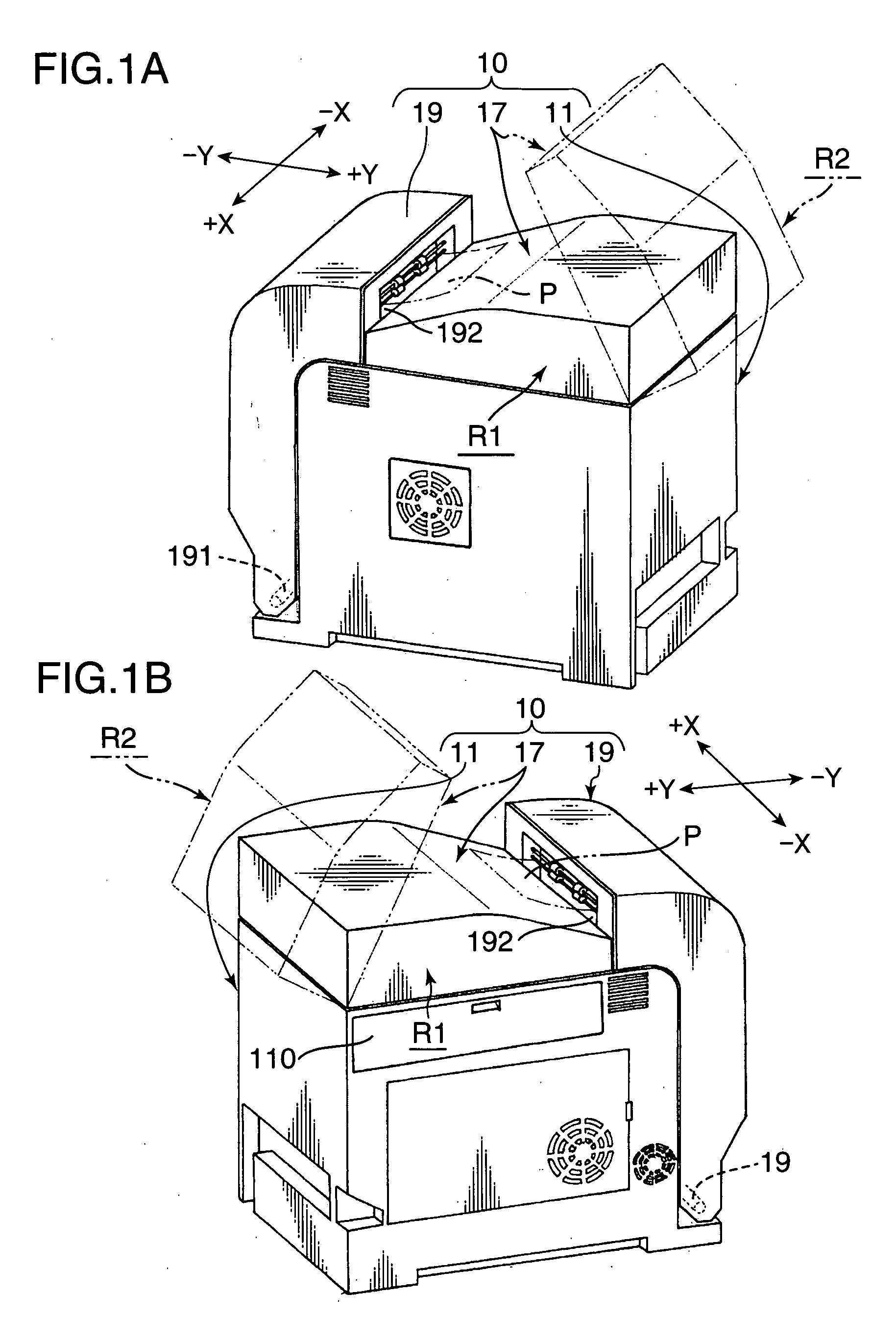
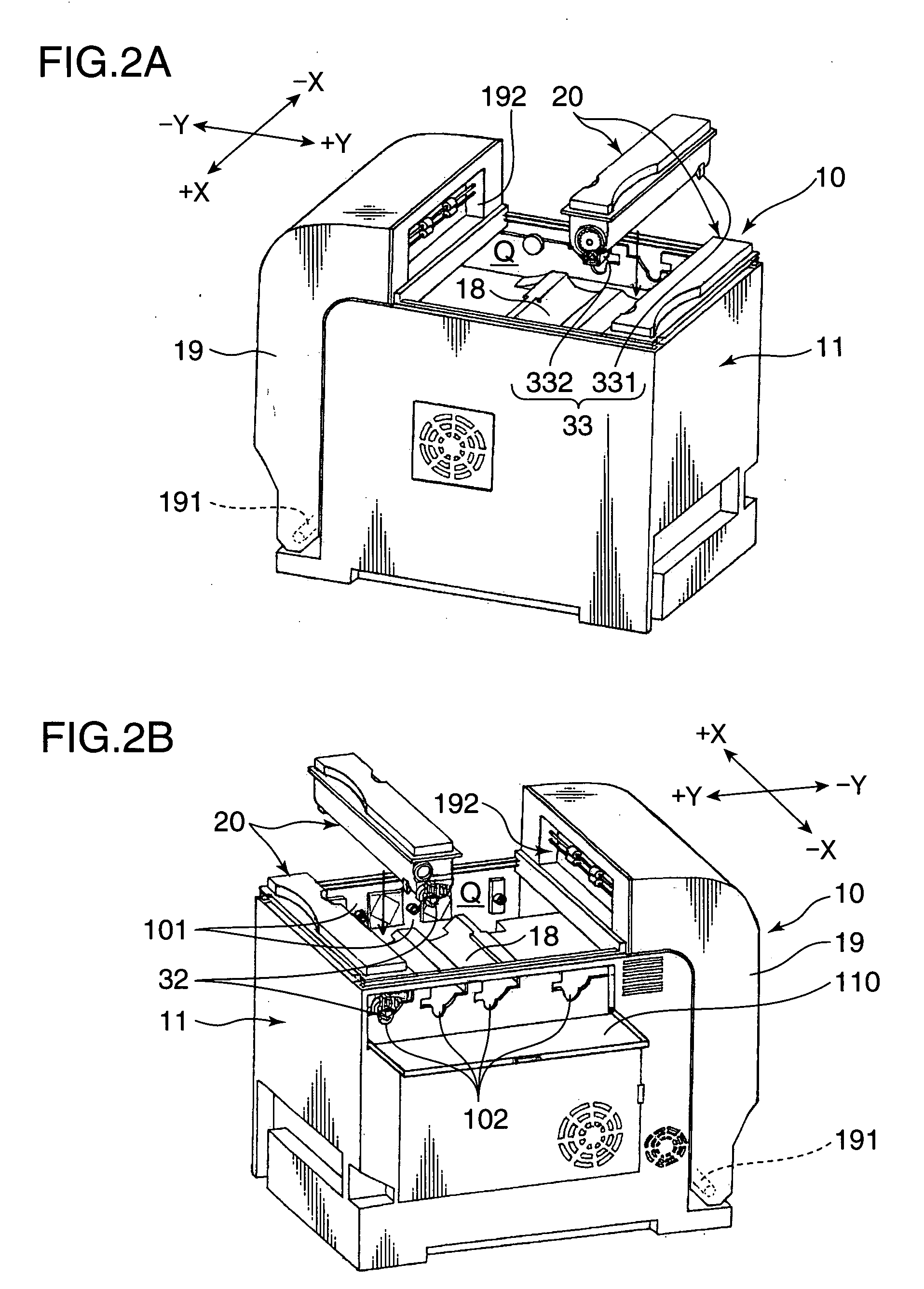
[0040]An image forming apparatus to which a toner container 20 according to a first embodiment of the present embodiment is provided will be briefly described with reference to FIGS. 1, 2, and 3, exemplifying a printer 10.
[0041]FIGS. 1A through 2B are external perspective views illustrating the printer 10. FIGS. 1A and 1B illustrate a paper output tray 17 installed in an apparatus main body 11; and FIGS. 2A and 2B illustrate the paper output tray 17 removed from the apparatus main body 11. FIGS. 1A through 2B are external perspective views illustrating the printer to which the toner container is provided. FIGS. 1A and 2A are perspective views when the printer is viewed from a right rear direction; and FIGS. 1B and 2B are perspective views when the printer is viewed from a left rear direction. FIG. 3 is a cross sectional view of an internal structure of the apparatus main body 11 viewed from a left side. In FIGS. 1A through 3, the X-X direction is referred to as a widthwise direction...
second embodiment
[0194]FIG. 19 is a partially cut exploded perspective view illustrating a toner container 20A according to a second embodiment. FIG. 20 is a partially cut perspective view of the assembled toner container 20A viewed from an obliquely upward front direction; and FIG. 21 is a perspective view of the toner container 20A viewed from an obliquely downward rear direction, respectively. In those drawings, components identical to those of the toner container 20 according to the first embodiment are given the same reference numbers. For ease of the explanation, explanation will be omitted or simplified with respect to the identical components.
[0195]The toner container 20A includes: a container 30A for containing toner; an agitator 40A for agitating toner within the container 30A; a conveying member 50 for conveying the toner within the container 30A; a shutter cylinder 60A for switching over a supply and non-supply of the toner; and a covering cap 70A for covering the left portion 314. The c...
PUM
 Abstract
Description
Claims
Application Information