Novel mounting device of municipal road indication board
A technology for municipal roads and installation devices, applied in the field of municipal road installations, can solve the problems of loosening of fasteners such as bolts, inconvenient disassembly and replacement, and shaking of signs, so as to reduce potential safety hazards, operate stably, and hold firmly. Effect
- Summary
- Abstract
- Description
- Claims
- Application Information
AI Technical Summary
Problems solved by technology
Method used
Image

Examples
Embodiment Construction
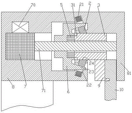
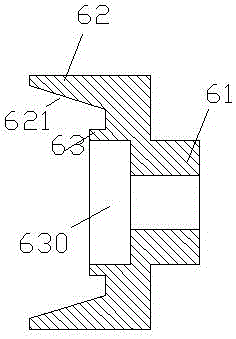
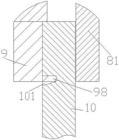
[0009] Combine below Figure 1-3 Examples of the present invention will be described in detail.
[0010] According to the embodiment of the present invention, the new installation device for the municipal road sign is used for installing and fixing the sign 10, including a clamping and fastening device installed on the column 1, and the clamping and fastening device includes a beam body 8 , the beam body 8 is equipped with a clamping motor 7, a clamping block 3, a rotating rod 71 connected to the output shaft of the clamping motor 7 and passing through the clamping block 3, and a screw threaded with the rotating rod 71 Cooperating clamping drive block 6, the lower end of the clamping block 3 is fixedly installed for clamping the left clamping arm 9 of the sign 10, and the right end of the beam body 8 is provided with a Cooperate with the right clamping arm 81, so that when the clamping motor 7 drives the clamping block 3 to move to the right, the left clamping arm 9 moves clo...
PUM
 Abstract
Description
Claims
Application Information