
Diamond cutting tool welding machine

A technology for diamond cutting and cutting tools, applied in manufacturing tools, welding equipment, welding equipment, etc., can solve the problems of lack of versatility, high equipment manufacturing and maintenance costs, error-prone, etc., to achieve convenient and easy adjustment, and ensure consistency. , the effect of high versatility

Active Publication Date: 2016-12-07
项大清
View PDF8 Cites 19 Cited by
  • Summary
  • Abstract
  • Description
  • Claims
  • Application Information

AI Technical Summary

Problems solved by technology

[0003] Diamond cutting tool welding machine is a kind of equipment that assists diamond cutter head to be welded on the tool matrix; As the diamond tool welding machine (application publication number CN103223538A) recorded in Chinese patent literature, because there are many types of diamond cutter heads and there are There are burrs of different lengths, the existing positioning seat of the cutter head has insufficient versatility, and the adjustment is relatively cumbersome, and the clamping is greatly affected by the burrs.
The diamond tool welding machine has the disadvantages of complex control procedures, error-prone, cumbersome debugging, and high equipment manufacturing and maintenance costs.

Method used


Image

  • Diamond cutting tool welding machine
  • Diamond cutting tool welding machine
  • Diamond cutting tool welding machine

Examples


Embodiment 1

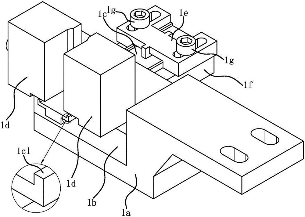
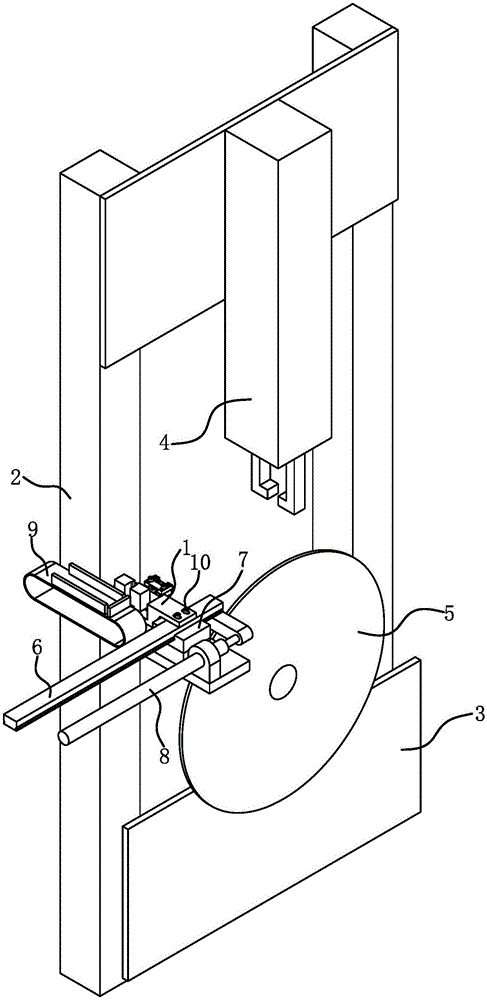
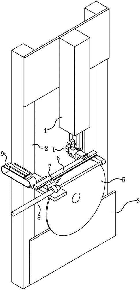
[0020] Such as figure 1 and figure 2 As shown, the diamond cutting tool welding machine includes a frame 2, a cutting tool substrate positioning tool 3, a cutting tool substrate clamping tool, a cutter head clamping device 4 and a diamond cutter head positioning seat 1.

[0021] According to the type of the cutting tool, the corresponding cutting tool base positioning tool 3 is selected; the cutting tool base positioning tool 3 is arranged on the frame 2 . The drawings in the description show that the cutting tool is a diamond saw blade, so the cutting tool base positioning tool 3 is the saw blade base positioning tool, and the cutting tool base clamping tool is the saw blade base clamping tool.

[0022] The cutter head clamping device 4 has a connecting seat, a cutter head clamping assembly and a lifting drive; Frame 2 is fixedly connected.

[0023] The diamond bit positioning seat 1 is located on one side of the bit holding device 4 , and the frame 2 is provided with a m...

Embodiment 2

[0036] The structure and principle of this embodiment are basically the same as that of Embodiment 1, and the basic similarities will not be described repeatedly, and only the differences will be described. The difference is that the diamond cutter head positioning seat 1 is located Directly ahead, then the guiding direction of the first guide rail 6 is set vertically to the clamping surface of the saw blade substrate clamping tool; that is, the first guide rail 6 is vertically arranged, and the mechanical moving device makes the diamond cutter head positioning seat 1 move horizontally left and right.

Embodiment 3

[0038] The structure and principle of this embodiment are basically the same as that of Embodiment 1, and the basic similarities will not be described redundantly. Only the differences will be described. The difference is that the mechanical moving device is a flexible manipulator, and the flexible manipulator includes a base and a mounting head. , the base is fixedly connected to the frame 2, and the base 1a of the diamond bit positioning seat 1 is fixedly connected to the installation head.


PUM


Abstract

The invention provides a diamond cutting tool welding machine and belongs to the technical field of work. The diamond cutting tool welding machine solves the problem that the manufacturing cost of an existing diamond cutting tool welding machine is high. The diamond cutting tool welding machine comprises a rack, a tool bit clamping device and a diamond tool bit positioning seat. The tool bit clamping device is located above a cutting tool base body positioning tool. The tool bit clamping device is provided with a connecting seat fixedly connected with the rack. The diamond tool bit positioning seat is located on one side of the tool bit clamping device. The rack is provided with a mechanical moving device capable of moving the diamond tool bit positioning seat to the position under the tool bit clamping device. The invention provides a diamond cutting tool welding machine of another arrangement structure. According to the diamond cutting tool welding machine, due to the fact that the mechanical structure and the control program are simplified, the precision of movement parts can be reduced, and especially the precision of the movement parts in the tool bit clamping device is reduced; and therefore the machining precision can be ensured, and the manufacturing cost can also be obviously reduced.

Description

technical field [0001] The invention belongs to the technical field of operations, and relates to welding, in particular to a diamond cutting tool welding machine. Background technique [0002] Diamond cutting tools are one of the commonly used cutting tools; diamond cutting tools include diamond saw blades, diamond gang saws and diamond thin-wall drills. [0003] Diamond cutting tool welding machine is a kind of equipment that assists diamond cutter head to be welded on the tool substrate; As the diamond tool welding machine (application publication number CN103223538A) recorded in Chinese patent literature, because there are many types of diamond cutter heads and there are For burrs of different lengths, the existing cutter head positioning seat has insufficient versatility, and the adjustment is relatively cumbersome, and the clamping is greatly affected by the burrs. Diamond tool welding machines have the disadvantages of complex control procedures, error-prone, cumbers...

Claims


Application Information

Patent Timeline
Patent Type & Authority Applications(China)
IPC IPC(8): B23K13/00B23K37/04B23K101/20
CPCB23K13/00B23K37/04
Inventor 项大清
Owner 项大清
Learn More