Automatic assembling method of light emitting diode (LED) lamp tube

A technology for automatic assembly of LED lamp tubes, applied to assembly machines, metal processing equipment, manufacturing tools, etc., can solve the problems of low assembly efficiency, high cost, and large labor consumption, and achieve high efficiency, low cost, and improved The effect of pass rate

Active Publication Date: 2013-08-07
GUANGZHOU LEDIA LIGHTING CO LTD
View PDF7 Cites 20 Cited by
  • Summary
  • Abstract
  • Description
  • Claims
  • Application Information

AI Technical Summary

Problems solved by technology

At present, the above-mentioned LED fluorescent tubes are assembled manually. Therefore, the efficiency of assembly is low, the labor consumption is large, and the cost is high.

Method used


Image

  • Automatic assembling method of light emitting diode (LED) lamp tube
  • Automatic assembling method of light emitting diode (LED) lamp tube
  • Automatic assembling method of light emitting diode (LED) lamp tube

Examples


Embodiment Construction

[0031] The present invention will be further described in detail below in conjunction with the accompanying drawings and specific embodiments.

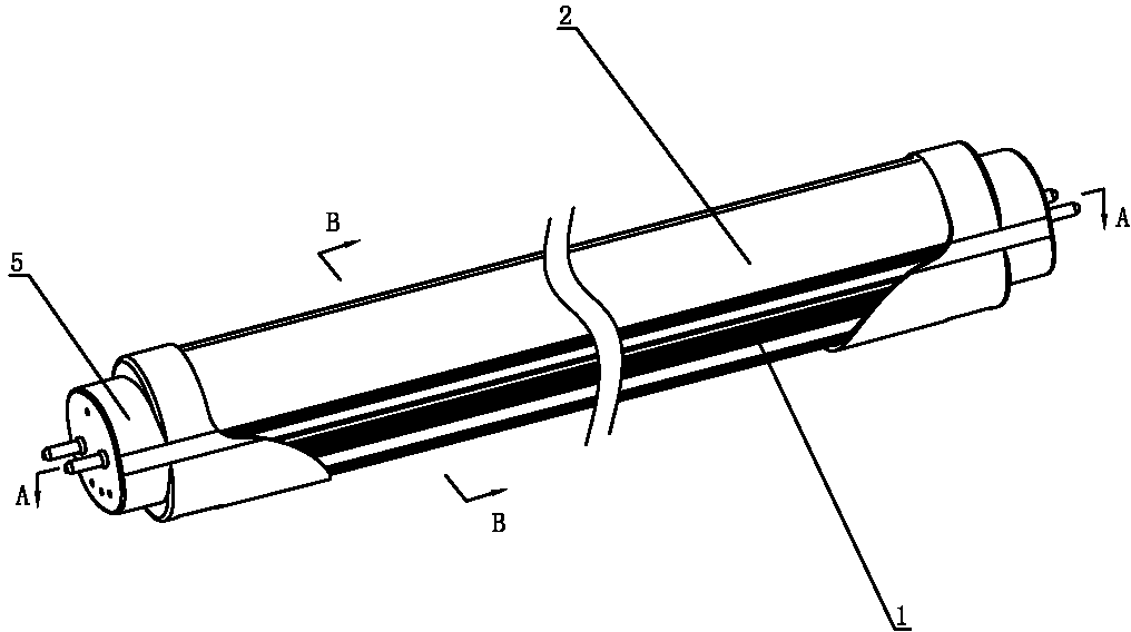
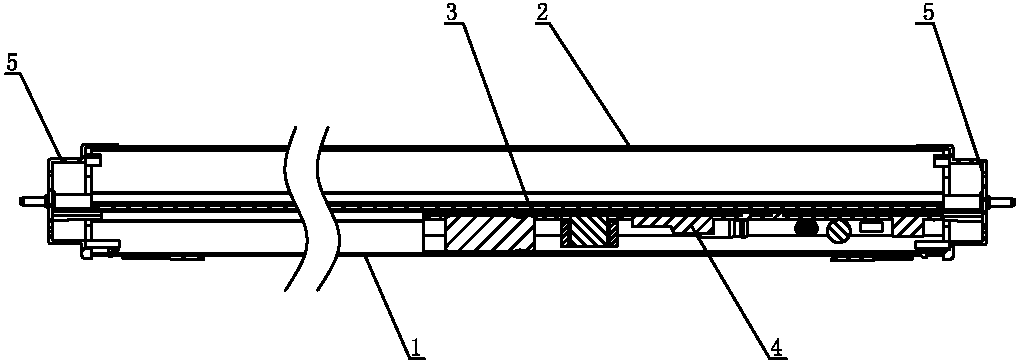
[0032] Such as Figure 1 to Figure 4 As shown, the LED lamp tube includes a housing 1 , a lampshade 2 , an LED light source 3 , a power supply 4 and a lamp holder 5 .

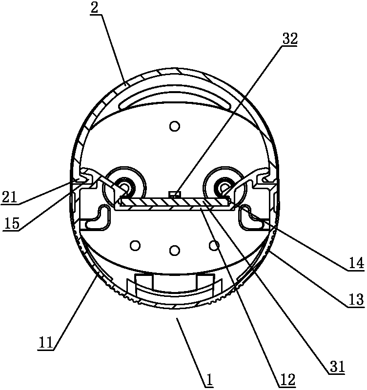
[0033] Such as Figure 4 As shown, the housing 1 includes a housing 11 and a bearing plate 12. The cross section of the housing 11 is U-shaped. The bearing plate 12 is arranged at the opening of the housing 11. The housing 11 and the bearing plate 12 are integrally formed. An accommodating chamber is formed between them, a bayonet (not shown) is provided on the shell, and a cooling rib 13 is provided on the outer wall of the shell 11 to improve the heat dissipation speed. The first card slot 14 and the second card slot 15 are formed on the outer end of the housing 11 .

[0034] A clip bar 21 is formed on the lampshade 2 , and the clip bar 21 is clipped in the second...


PUM


Abstract

The invention discloses an automatic assembling method of a light emitting diode (LED) lamp tube. The automatic assembling method includes that a mechanical arm is controlled to take a casing onto a special clamp located on an automatic conveyor; (2) the special tool clamping the casing is conveyed to a first station; (3) the mechanical arm is controlled to take and insert an LED light source into a first clamp slot; (4) the casing is conveyed to the next station; (5) the mechanical arm is controlled to take a lampshade and insert a clamp strip of the lampshade into a second clamp slot; (6) the casing is conveyed to the next station; (7) a lead wire is welded between the LED light source and an electrode; (8) the casing is conveyed to the next station; (9) the mechanical arm is controlled to take a lamp head, the lamp head is arranged at two ends of the casing, the casing and two ends of the lampshade are clamped into the clamp slots, and a buckle is clamped onto a bayonet at the moment to complete installation of the LED lamp tube; and (10) the LED lamp tube is detached from the special clamp. The automatic assembling method improves assembling efficiency of the LED lamp tube and reduces cost.

Description

technical field [0001] The invention relates to an assembly method of an LED lamp tube. Background technique [0002] The current LED fluorescent tube is mainly composed of a housing, a lampshade, an LED light source and a lamp holder. The lampshade is clamped on the housing, the LED light source is installed in the housing, and the lamp holder is installed at the end and connected by glue. At present, the above-mentioned LED fluorescent tubes are assembled manually, therefore, the efficiency of assembly is low, the consumption of labor is large, and the cost is high. Contents of the invention [0003] In order to improve the assembly efficiency of LED lamp tubes and reduce costs, the present invention provides an automatic assembly method for LED lamp tubes. [0004] In order to achieve the above purpose, an automatic assembly method for LED lamp tubes is provided. The LED lamp tube includes a housing, a lampshade, an LED light source and a lamp holder; the inner wall of...

Claims


Application Information

Patent Timeline
Patent Type & Authority Applications(China)
IPC IPC(8): B23P21/00
Inventor 刘杰琼吕天刚
Owner GUANGZHOU LEDIA LIGHTING CO LTD
Why Eureka
Try Eureka