
Automatic screw and nut combination locking device

An automatic combination, screw and nut technology, applied in the direction of metal processing, metal processing equipment, manufacturing tools, etc., can solve the problems of boring work content, low efficiency, and high work intensity of workers, so as to improve core competitiveness, improve efficiency and Accuracy and reduction of assembly man-hours

Active Publication Date: 2014-01-29
SHENZHEN INST OF ADVANCED TECH CHINESE ACAD OF SCI
View PDF7 Cites 40 Cited by
  • Summary
  • Abstract
  • Description
  • Claims
  • Application Information

AI Technical Summary

Problems solved by technology

[0005] To sum up, at present, the combined locking method of domestic screw nuts has not yet been realized.
On the one hand, manual assembly is used. For this assembly method, the product production cycle is long, the efficiency is low, the work intensity of the workers is high, the work content is boring, the cost of the enterprise is also high, and the consistency of the assembled products is relatively high. Difference
On the other hand, if the existing single-function locking nut or locking screw device is adopted, such as an automatic screw screw machine and an automatic nut screw machine, a double-station assembly process is required, that is, the automatic screw screw machine is used to screw the screw, and then Then use the automatic nut tightening machine to lock the nut
This method of automated assembly takes a long time and increases the complexity of automated assembly

Method used


Image

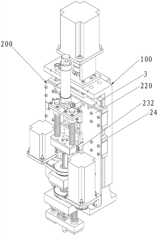
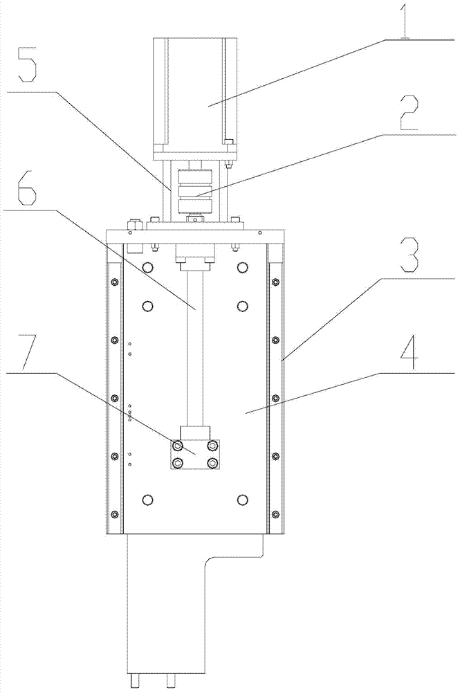
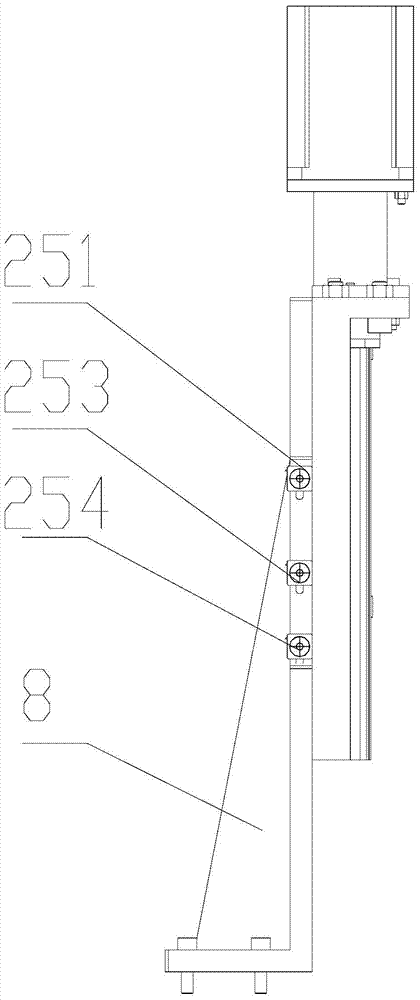
  • Automatic screw and nut combination locking device
  • Automatic screw and nut combination locking device
  • Automatic screw and nut combination locking device

Examples


Embodiment Construction

[0025] In order to make the object, technical solution and advantages of the present invention clearer, the present invention will be further described in detail below in conjunction with the accompanying drawings and embodiments. It should be understood that the specific embodiments described here are only used to explain the present invention, not to limit the present invention.

[0026] It should be noted that when an element is referred to as being “fixed on” or “disposed on” another element, it may be directly on the other element or there may be an intervening element at the same time. When an element is referred to as being "connected to" another element, it can be directly connected to the other element or intervening elements may also be present.

[0027] It should also be noted that the orientation terms such as left, right, up, and down in this embodiment are only relative concepts or refer to the normal use state of the product, and should not be regarded as limiti...


PUM


Abstract

The invention is applicable to the field of assembly technologies for screws and nuts, and discloses an automatic screw and nut combination locking device which comprises a fixing assembly and a sliding assembly. The sliding assembly comprises a sliding plate, the sliding plate is slidably connected to the fixing assembly, and a sliding plate driving assembly is arranged on the fixing assembly; a screw locking assembly and a nut locking assembly are connected onto the sliding plate, the screw locking assembly comprises a screwdriver, a screw rotation driving assembly and an axial driving assembly, the screw rotation driving assembly is used for driving the screwdriver to peripherally rotate, and the axial driving assembly is used for driving the screwdriver to vertically slide; the nut locking assembly comprises a nut locking sleeve and a nut rotation driving assembly, the nut rotation driving assembly is used for driving the nut locking sleeve to rotate, and the screwdriver and the nut locking sleeve are coaxially arranged. The automatic screw and nut combination locking device has the advantages that a screw and a nut can be assembled at one station, so that the product assembly working hours can be greatly reduced, the assembly efficiency and the assembly precision can be improved, the cost can be reduced for an enterprise, and the core competitiveness of the enterprise can be improved.

Description

technical field [0001] The invention belongs to the technical field of screw nut assembly, and in particular relates to a screw nut automatic combination locking device. Background technique [0002] At present, there are various structural forms of screw locking devices or nut locking devices at home and abroad, but in production practice, there are many special working conditions, such as occasions where screws and nuts need to be locked at the same time (especially in the tuning of microwave filters When the screw is assembled, the screw and the nut need to be locked at the same time). Generally, there are many and complicated installation holes for each workpiece. Manual installation is inefficient and the product consistency is not good. [0003] The automatic locking device of screws and nuts plays a vital role in the entire field of automated assembly, and with the rapid development of today's industrialization, the application of screws and nuts is more frequent. A...

Claims


Application Information

Patent Timeline
IPC IPC(8): B23P19/06
CPCB23P19/06
Inventor 于文泽王书付汪芳胜刘建坤顾以进罗昌杰何凯杜如虚
Owner SHENZHEN INST OF ADVANCED TECH CHINESE ACAD OF SCI
Learn More