Dynamoelectric machine

a dynamoelectric machine and dynamoelectric technology, applied in the direction of magnetic circuit rotating parts, magnetic circuit shape/form/construction, windings, etc., can solve the problems of increasing the rotor inertia, and invariably increasing the size of the alternator, so as to reduce assembly man-hours, facilitate the holding of permanent magnets, and strengthen the holding construction

Active Publication Date: 2010-08-19
MITSUBISHI ELECTRIC CORP
View PDF17 Cites 13 Cited by
  • Summary
  • Abstract
  • Description
  • Claims
  • Application Information

AI Technical Summary

Benefits of technology

[0039]According to the present invention, permanent magnets are disposed so as to be housed and held in magnet housing portions of a bobbin so as to face inner circumferential surfaces near tip ends of claw-shaped magnetic pole portions. Thus, because displacement of the claw-shaped magnetic pole portions that results from centrifugal forces or thermal expansion will not affect the permanent magnets, the magnet holding construction is strengthened, occurrences of cracking or chipping of the permanent magnets that result from the displacement of the claw-shaped magnetic pole portions are suppressed, and holding of the permanent magnets is also facilitated. The permanent magnets are held by the bobbin, and can be mounted to the pole core together with a field winding during assembly, reducing assembly man-hours, and improving assembly. Because the permanent magnets are positioned radially inside the claw-shaped magnetic pole portions, increases in moment of inertia that accompany disposition of the permanent magnets are reduced. In addition, centrifugal forces that act on the permanent magnets are also reduced, facilitating holding of the permanent magnets.
[0040]Because the permanent magnets are disposed so as to face inner circumferential surfaces near tip ends of the claw-shaped magnetic pole portions, the permanent magnets are positioned radially inside the claw-shaped magnetic pole portions and are not heated by induction directly due to stator slot harmonics, enabling thermal demagnetization to be prevented. Because the permanent magnets are thermally insulated from the field winding and the pole core by the bobbin, they are less likely to be affected by transfer of heat that is generated in the field winding, enabling thermal demagnetization to be prevented since magnet temperature will not increase.
[0041]In addition, because the permanent magnets are magnetically oriented in a reverse direction to the orientation of the magnetic field produced by the field coil, the magnetic field circuits formed by the permanent magnets are closed inside the rotor, suppressing the occurrence of induced voltages during no-load de-energization even if magnet volume is increased.

Problems solved by technology

If attempts are made to answer these demands within the scope of conventional design, the alternators are invariably increased in size.
Increases in alternator size are undesirable since the weight of and space occupied by such alternators is increased.
Increases in alternator size are also known to give rise to new problems such as increased rotor inertia, and engine speed fluctuations and alternator inertial torque interacting and leading to belt vibration and slippage.
In other words, if the two are placed in point contact, local stresses may be concentrated on the magnets, and the magnets may be damaged.
Because raising magnet processing precision is difficult in mass-produced products, it is also possible to consider means for ensuring external shape precision of the magnets using SUS plates, etc., instead, but these lead to enormous costs.
Realistically, ensuring such parts precision increases costs significantly during mass production of rotors.
In addition, even if static shape precision is adapted in this manner, magnet holding in automotive alternators is still difficult.
However, axial positions of the permanent magnets between the claw-shaped magnetic pole portions are easily misaligned when the pole core bodies are put together, giving rise to imbalances in magnet positions between the magnetic poles.
Thus, there have been problems such as steps for balancing the rotor itself being increased, and electromagnetic noise occurring due to imbalances in magnetic flux during rotation.
One problem is that if even a portion of a magnet is heated by induction and reaches a high temperature locally, heat will transfer to the entire magnet, and the magnet will be thermally demagnetized.
Portions of the magnets or magnet holding metal fittings are also exposed at the rotor surface facing the stator in the conventional improved magnet holding construction, making thermal demagnetization of the magnets similarly problematic.
In alternators to which a Lundell rotor is mounted, heat is generated in the field coil, and one problem has been that that heat is transferred to the permanent magnets through the rotor, exacerbating temperature increases in the magnets, and causing thermal demagnetization.
The above-mentioned conventional improved magnet holding construction has problems of induced voltage during no-load de-energization.
However, since automotive engines have a variable speed range of approximately 1:10, if, for example, the maximum engine speed is ten times that of idling, the one- or two-volt induced voltages from the magnets may exceed the system voltage of the vehicle and have adverse effects on other on-board equipment.
One problem is that when the direction of flow of the current becomes bidirectional instead of unidirectional, a bidirectional circuit that incorporates an H-bridge is required instead of simple chopper control, increasing the number of components, and raising product costs.
Furthermore, unlike a normal field, it is necessary to start this reverse field swiftly in response to increases in engine speed, but since a coil that has a high impedance of several hundred turns is used so as to be able to control the field using a small current of approximately several amperes, it is currently difficult to make the reverse field current flow instantaneously.
If the number of field turns is reduced in order to avoid this, new problems arise such as the electric current value of the control power source itself also being increased, increasing control element capacity, and raising product costs.

Method used


Image

  • Dynamoelectric machine
  • Dynamoelectric machine
  • Dynamoelectric machine

Examples


embodiment 1

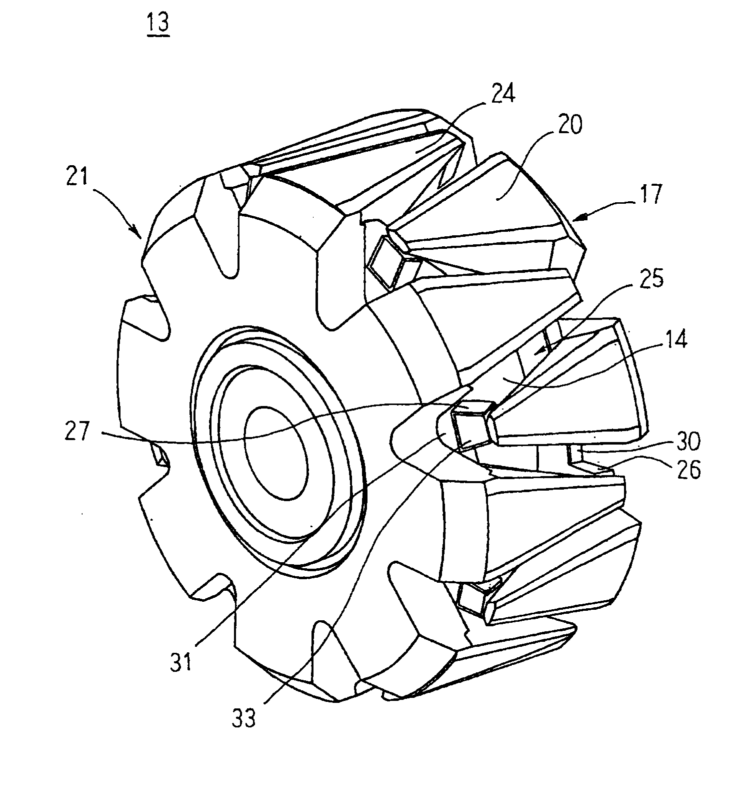
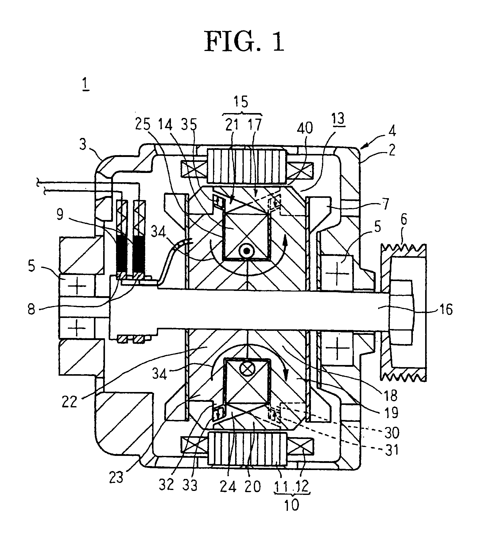
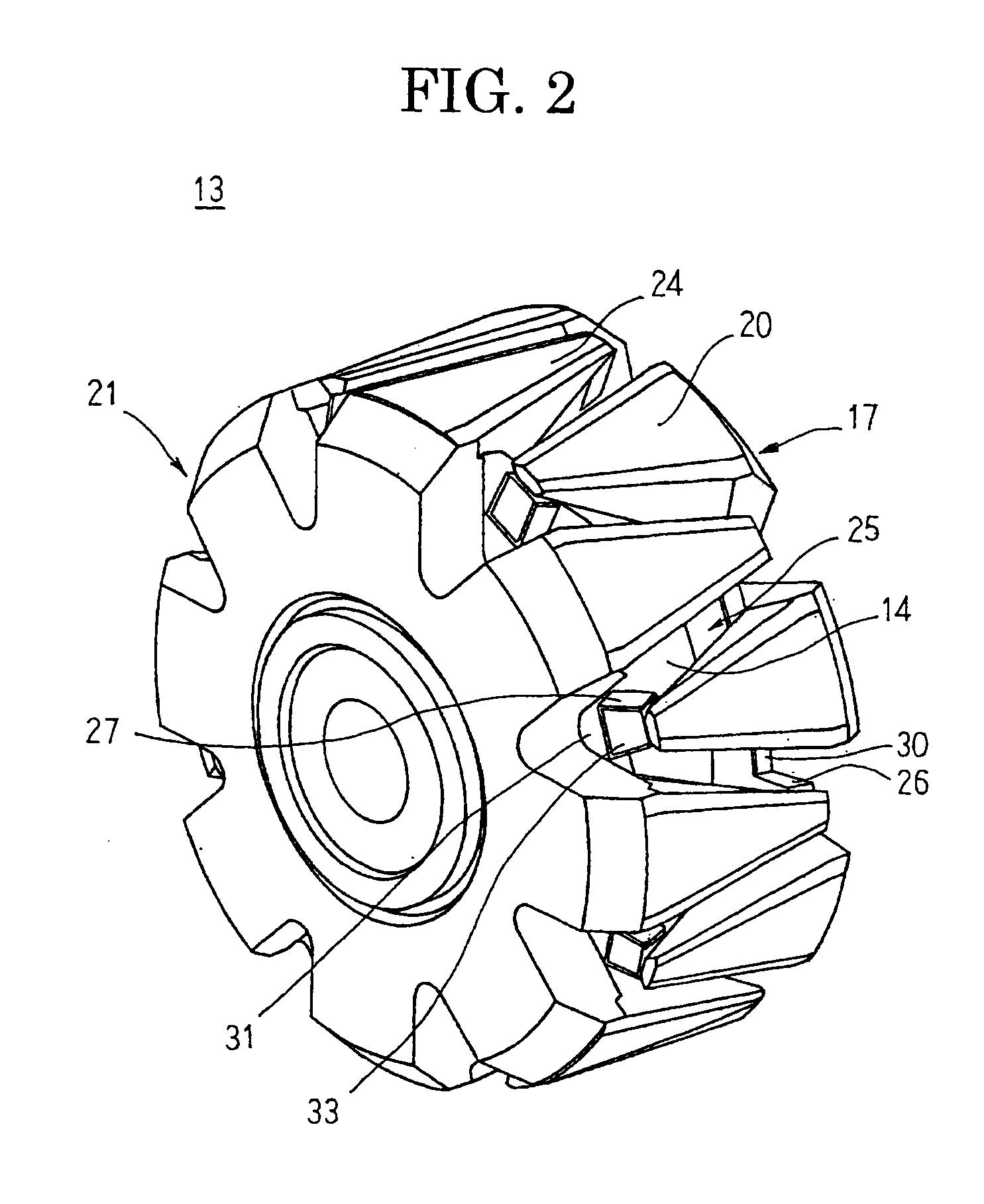
[0066]FIG. 1 is a cross section that schematically shows an automotive alternator according to Embodiment 1 of the present invention, FIG. 2 is a perspective that shows a rotor that can be used in the automotive alternator according to Embodiment 1 of the present invention, FIG. 3 is a perspective that shows a bobbin into which permanent magnets have been incorporated in the automotive alternator according to Embodiment 1 of the present invention, and FIGS. 4 and 5 are respective schematic diagrams for explaining flow of magnetic flux in the automotive alternator according to Embodiment 1 of the present invention.

[0067]In FIGS. 1 through 3, an automotive alternator 1 includes: a case 4 that is constituted by a front bracket 2 and a rear bracket 3 that are each made of aluminum in an approximate cup shape; a rotor 13 that is rotatably disposed inside the case 4 such that a shaft 16 is supported by means of bearings 5 in the case 4; a pulley 6 that is fixed to an end portion of the sh...

embodiment 2

[0101]FIG. 8 is a perspective that shows a rotor that can be used in an automotive alternator according to Embodiment 2 of the present invention, and FIG. 9 is an exploded perspective that explains a configuration of the rotor that can be used in the automotive alternator according to Embodiment 2 of the present invention.

[0102]In FIGS. 8 and 9, first magnet seat portions 30A are disposed so as to project integrally on portions of a first yoke portion 19 between adjacent first claw-shaped magnetic pole portions 20, and outer circumferential surfaces thereof are formed into cylindrical surfaces that have an axial center of a first pole core body 17A as a central axis. First interfitting grooves 28 that function as interfitting recess portions that have trapezoidal cross sections perpendicular to the central axis of the first pole core body 17A are recessed into portions of outer circumferential surfaces of the first magnet seat portions 30A that face inner circumferential surfaces ne...

embodiment 3

[0107]FIG. 10 is a cross section that schematically shows an automotive alternator according to Embodiment 3 of the present invention, and FIG. 11 is a perspective that shows a bobbin into which permanent magnets have been incorporated in the automotive alternator according to Embodiment 3 of the present invention.

[0108]In FIGS. 10 and 11, first magnet seat portions 30B are disposed so as to project integrally on portions of a first yoke portion 19 between adjacent first claw-shaped magnetic pole portions 20, and outer circumferential surfaces thereof are formed into flat surfaces that are tangential to cylindrical surfaces that have an axial center of a first pole core body 17B as a central axis. First magnet housing portions 26B are prepared into angular U-shaped tubular bodies in which a cross section that is perpendicular to a central axis of a drum portion 25a of a bobbin 25B is trapezoidal, and axially inner sides are closed by a flange portion 25b. Bottom surfaces of the angu...


PUM


Abstract

A dynamoelectric machine includes first and second magnet seat portions disposed to project from portions of first and second yoke portions that face respective inner circumferential surfaces near tip ends of second and first claw-shaped magnetic pole portions, and magnet housing portions disposed integrally to extend axially outward from outer circumferential portions of a pair of flange portions of a bobbin, extend near the first and second yoke portions that face the inner circumferential surfaces near the tip ends of the first and second claw-shaped magnetic pole portions, and be held by the first and second magnet seat portions. First and second permanent magnets are housed and held in the first and second magnet housing portions, are disposed to face the inner circumferential surfaces near the tip ends of the second and first claw-shaped magnetic pole portions, and the first and second permanent magnets are respectively magnetically oriented in a reverse direction to a direction of a magnetic field that the field coil produces.

Description

TECHNICAL FIELD[0001]The present invention relates to a dynamoelectric machine such as an automotive alternator, etc., and relates particularly to a Lundell rotor construction in which permanent magnets are mounted.BACKGROUND ART[0002]Automotive alternators that use Lundell rotors have been used in automobiles for decades. Loads from electrical equipment that is mounted due to environmental issues have been increasing rapidly in recent years, and further increases in generated power are being sought from Lundell rotors. If attempts are made to answer these demands within the scope of conventional design, the alternators are invariably increased in size. Increases in alternator size are undesirable since the weight of and space occupied by such alternators is increased. Increases in alternator size are also known to give rise to new problems such as increased rotor inertia, and engine speed fluctuations and alternator inertial torque interacting and leading to belt vibration and slip...

Claims


Application Information

Patent Timeline
Patent Type & Authority Applications(United States)
IPC IPC(8): H02K1/28H02K1/22H02K21/04
CPCH02K21/044
Inventor YOSHIZAWA, TOSHIYUKIINOUE, MASAYASHINKAWA, KANJIMORITA, MASAOHAZEYAMA, MORIYUKIAKITA, HIROYUKINISHIMURA, SHINJIMURATA, NORIHIRO
Owner MITSUBISHI ELECTRIC CORP
Why Eureka
Try Eureka