Connector

a technology of connecting parts and connectors, applied in the direction of coupling devices, two-part coupling devices, electrical apparatus, etc., can solve the problems of increasing the stability of the stabilizing support at the contact point cannot be guaranteed, and the positional relation between each insulating member and the contact point is less likely to be stable, so as to reduce the type and number of parts, reduce assembly man-hours, and reduce the manufacturing cost of connectors

Inactive Publication Date: 2012-09-25
HITACHI CABLE
View PDF18 Cites 13 Cited by
  • Summary
  • Abstract
  • Description
  • Claims
  • Application Information

AI Technical Summary

Benefits of technology

[0013]In addition, since each of the plural insulating members is separate from the connecting terminal, there is a problem that the type and number of parts increase, and thus, assembly man-hours increases when such a connection structure is applied to a connector. Therefore, the inventors tried, if possible, to reduce the assembly man-hours so as to eventually lead to reduction in manufacturing cost.
[0014]Accordingly, it is an object of the invention to provide a technique that can offer the stabilizing support at the contact point for the connector with the structure to sandwich the contact point between the insulating members, and reduce the assembly man-hours by reducing the type and number of parts so as to eventually reduce the manufacturing cost.(1) According to one embodiment of the invention, a connector comprises:
[0025]According to one embodiment of the invention, a connector is constructed such that an insulating member is integrated with a first connecting terminal. Therefore, the integration of the insulating member and the first connecting terminal can offer the stabilizing support at the contact point against the vibration of a vehicle. On the other hand, the insulating member and the first connecting terminal can be handled as one component. Thereby, it is possible to reduce the type and number of parts, and thus to reduce the assembly man-hours for assembling the connector. In addition, the connector is constructed such that the insulating members each have a same shape and size. As a result, it is possible to reduce the manufacturing cost of the connector.

Problems solved by technology

However, the connection structure of Japanese patent No. 4037199 may include the following problems.
In other words, since the insulating member and the connecting terminal move separately, a problem may arise that the positional relation between each insulating member and the contact point is less likely to be stable and the stabilizing support at a contact point cannot be ensured under the technique of sandwiching the contact point between the insulating members.
In addition, since each of the plural insulating members is separate from the connecting terminal, there is a problem that the type and number of parts increase, and thus, assembly man-hours increases when such a connection structure is applied to a connector.

Method used


Image

  • Connector
  • Connector
  • Connector

Examples


Embodiment Construction

[0035]A preferred embodiment of the invention will be described below in conjunction with the appended drawings.

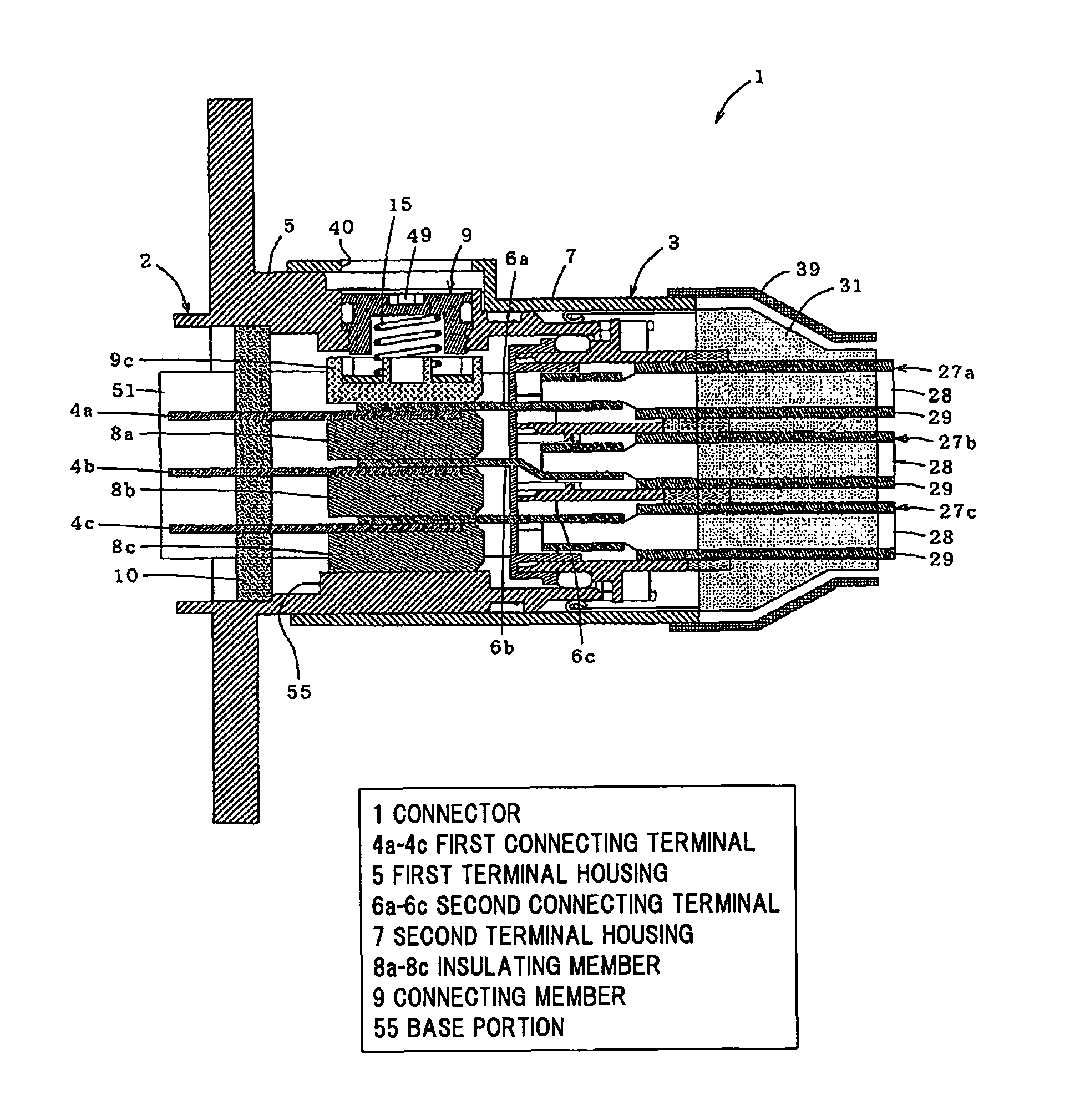
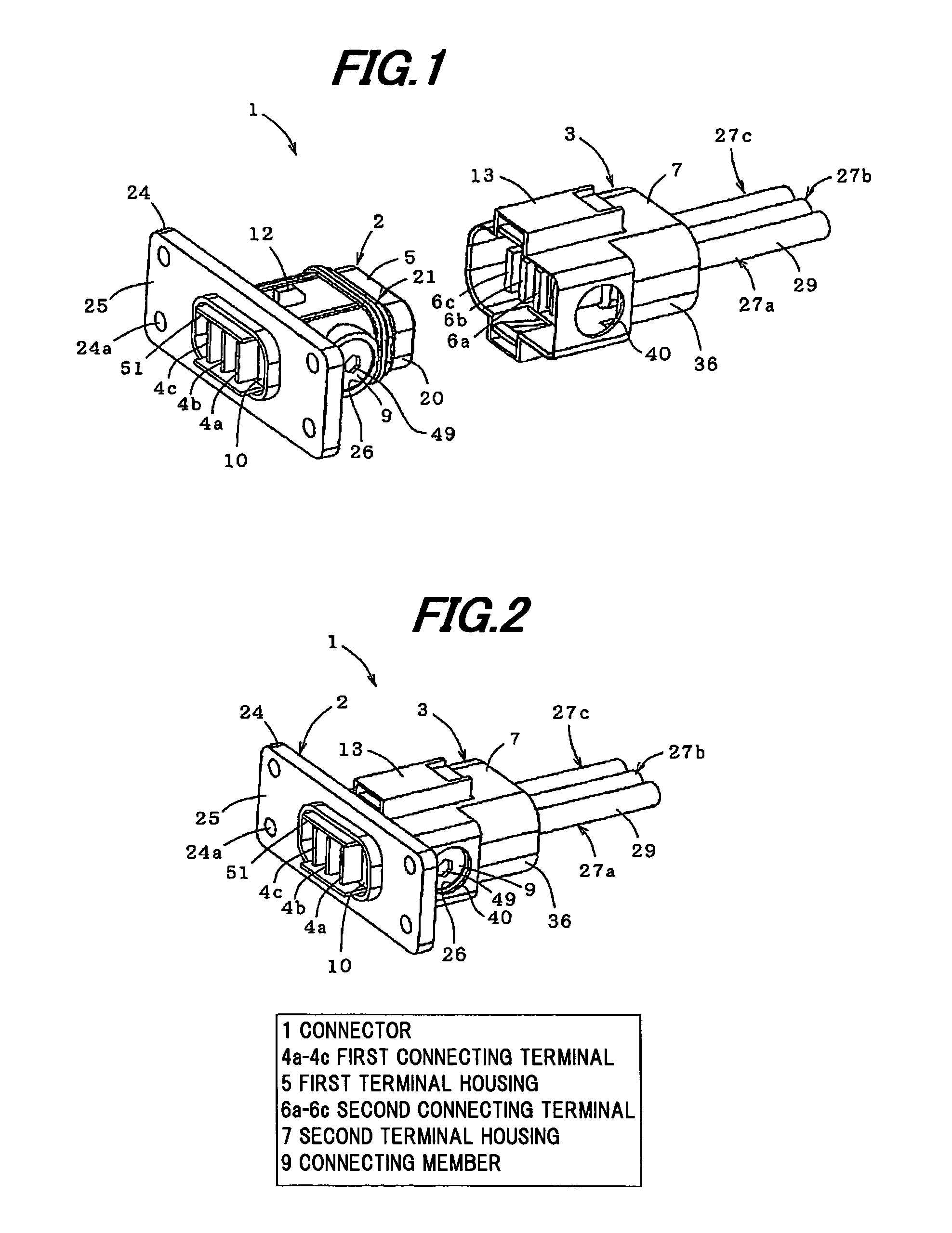
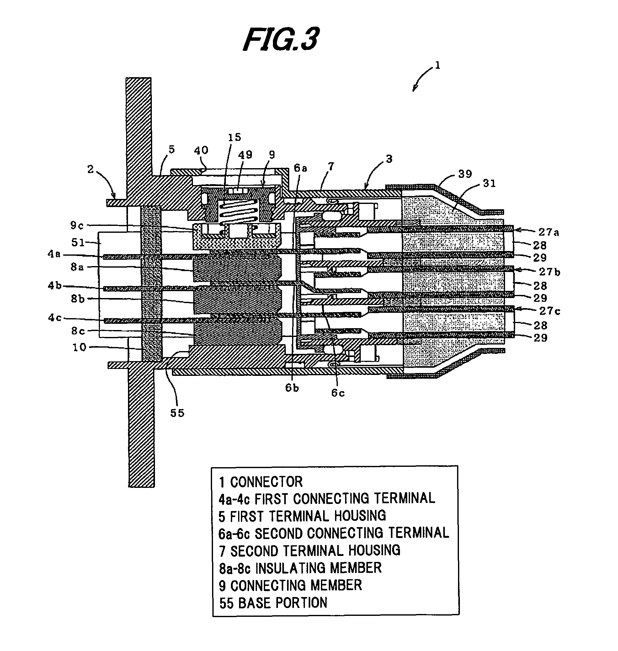
[0036]FIG. 1 is a perspective view showing first and second connector portions of a connector in a preferred embodiment of the invention, FIG. 2 is a perspective view showing the connector when the first connector portion is fitted to the second connector portion, and FIG. 3 is a cross sectional view thereof. Note that, a braided shield 31 and a rubber boot 39 which will be described later are omitted in FIGS. 1 and 2.

[0037]As shown in FIGS. 1 to 3, a connector 1 of the present embodiment is composed of a first connector portion 2 and a second connector portion 3, and plural power lines are connected at a time by fitting the connector portions 2 and 3 together.

[0038]More specifically, the connector 1 is provided with the first connector portion 2 having a first terminal housing 5 for housing a first inner housing 10 which holds plural (three) first connecting terminals (ma...


PUM


Abstract

A connector includes a first terminal housing for housing a first inner housing that houses a plurality of first connecting terminals vertically aligned at predetermined intervals, a second terminal housing for housing a second inner housing that houses a plurality of second connecting terminals vertically aligned at predetermined intervals, a plurality of insulating members that are aligned and housed in the first terminal housing and are fixed to the lower surfaces of the plurality of first connecting terminals, and a connecting member for collectively fixing and electrically connecting the plurality of first connecting terminals to the plurality of second connecting terminals at each contact point by pressing an upper surface of one of the second connecting terminals at an uppermost part of the laminated structure. The plurality of insulating members each have a same shape and size.

Description

[0001]The present application is based on Japanese Patent Application No. 2010-189400 filed on Aug. 26, 2010, the entire contents of which are incorporated herein by reference.BACKGROUND OF THE INVENTION[0002]1. Field of the Invention[0003]The invention relates to a connector which is used for, e.g., an eco-friendly car such as a hybrid car and an electric car, in particular, to a connector which may be potentially employed for a connection of a power harness used for transmitting a large amount of power.[0004]2. Description of the Related Art[0005]A power harness is used for connecting between devices such as between a motor and an inverter or between an inverter and a battery in, e.g., a hybrid car or an electric car, which has made significant progress in recent years, for transmitting a large amount of power. The power harness is at one end thereof provided with a connector in a two-block structure composed of, e.g., a male connector portion provided with a male terminal as well...

Claims


Application Information

Patent Timeline
Patent Type & Authority Patents(United States)
IPC IPC(8): H01R13/60
CPCH01R13/193H01R24/62H01R13/639H01R2107/00
Inventor KATAOKA, YUTATAKEHARA, HIDEAKIFUKUDA, KUNIHIROSUZUKI, SACHIOUMETSU, JUNHAYASHI, SHINYA
Owner HITACHI CABLE
Why Eureka
Try Eureka