Cavity filter, duplexer, combiner and transmission zero frequency debugging method for cavity filter

A cavity filter and cavity technology, applied in the field of communication, can solve the problems of high filter production cost, high purchase price, increased material cost, etc., and achieve the effect of reducing the cost of raw material procurement, reducing the probability of errors, and saving assembly man-hours.

Inactive Publication Date: 2012-09-19
吴芬
View PDF4 Cites 14 Cited by
  • Summary
  • Abstract
  • Description
  • Claims
  • Application Information

AI Technical Summary

Problems solved by technology

[0006] 1. The assembly of coupling probe 2' is complex and the production cost of the filter is high
The cavity filter 1' with the above-mentioned structure has high requirements on the precision of the coupling spacing S, but in mass production, due to the precision of the processing equipment and errors in the assembly process, coupled with the coupling probe 2', there is almost no adjustability , which makes it difficult to maintain the consistency of the coupling spacing S, which increases the debugging time of the filter, and some even need to rework, reassemble or replace coupling probes of different lengths to meet the overall index of the filter, resulting in additional production costs. Increase
[0007] 2. Since the raw material of the media card holder is PTFE (Poly Tetra Fluoro Ethylene), its purchase price is relatively expensive, and the processing technology of the card holder is complicated, resulting in a high price of the media card holder, which increases the cost of materials
[0008] 3. Due to the limitation of the structural characteristics of the coupling probe 2', for the structural layout of "one" arrangement such as comb filter, it is difficult to realize the transmission zero point, thus limiting the application range of the cross-coupling method in the cavity filter

Method used


Image

  • Cavity filter, duplexer, combiner and transmission zero frequency debugging method for cavity filter
  • Cavity filter, duplexer, combiner and transmission zero frequency debugging method for cavity filter
  • Cavity filter, duplexer, combiner and transmission zero frequency debugging method for cavity filter

Examples


Embodiment 1

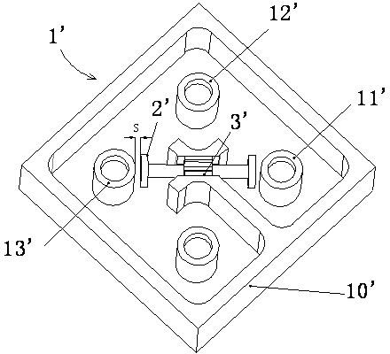
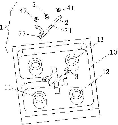
[0028] Please refer to image 3 , Figure 4 As shown, Embodiment 1 of the present invention provides a cavity filter 1 , including: a cavity 10 , resonators 11 , 12 , 13 and a coupling jumper 2 .

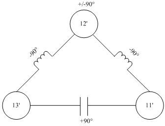
[0029] The resonators 11, 12, and 13 are placed in the cavity 10, and are arranged in a right triangle in this embodiment. The resonators 11 and 13 are respectively located at both ends of the hypotenuse of the right triangle, and are respectively connected to signal input and output terminals to form a resonator 11. →12→13 for the main transmission path, and the resonator 11→13 for the transmission secondary path.

[0030] The coupling jumper 2 further includes a coupling part 21 and an assembly part 22 . The length of the coupling part 21 is λ / 4, where λ represents the wavelength corresponding to the transmission zero frequency required by design. The open circuit of the λ / 4 wavelength terminal is equivalent to the inductance of the inner conductor and the series connection of ...

Embodiment 2

[0037] For the comb cavity filter, the resonators are arranged in a "one" shape, which cannot be implemented in the coupling probe method in the prior art. For this, please refer to Figure 6 , Figure 7 As shown, Embodiment 2 of the present invention provides a cavity filter 6 , including: a cavity 60 , resonators 61 , 62 , 63 and coupling jumpers 7 .

[0038] The resonators 61, 62, 63 are placed in the cavity 60, arranged in a "one" shape in this embodiment, and the resonators 61 and 63 are respectively located at both ends of the "one" shape, and connected to the signal input and output terminals to form The transmission main path of the resonator 61→62→63, and the transmission secondary path of the resonator 61→63.

[0039] The coupling jumper 2 further includes a coupling part 21 and an assembly part 22 . The length of the coupling part 21 is λ / 4, where λ represents the wavelength corresponding to the transmission zero frequency required by design. Same as the first e...

Embodiment 3

[0047] In the cavity filters provided by Embodiments 1 and 2 of the present invention, capacitive cross-coupling is introduced into the transmission secondary path, so that a transmission zero point is generated on the left side (low end) of the transmission passband of the cavity filter. Although the transmission zero frequency required by the design can be basically achieved by controlling the length of the coupling part (21, 71) of the coupling jumper (2, 7), but considering the inevitable errors generated in the process of production, processing and assembly, for To more accurately make the transmission zero frequency meet the design requirements, Embodiment 3 of the present invention provides a transmission zero frequency debugging method, including:

[0048] Judging the difference between the actual transmission zero frequency and the designed transmission zero frequency;

[0049] Move the actual transmission zero frequency to the right by raising the height of the jumpe...


PUM


Abstract

The embodiment of the invention provides a cavity filter, which comprises a cavity, a first resonator, a second resonator, a third resonator, a main transmission path, a secondary transmission path and a coupling jumper, wherein the first, second and third resonators are sequentially arranged in the cavity; the main transmission path is led to the third resonator from the first resonator through the second resonator; the secondary transmission path is led to the third resonator from the first resonator; the coupling jumper is arranged between the first and third resonators along the secondary transmission path; and one end of the coupling jumper is assembled on the third resonator, and the other end of the coupling jumper is assembled on the cavity. The cavity filter is easy to assemble, so that work hours for assembly are reduced, requirements for the skills of an assembly operator are greatly lowered, and the error probability of the assembly operator is reduced. Moreover, the coupling jumper is formed by stamping a metal plate, so that the cavity filter is high in consistency and low in cost, the production cost and raw material purchasing cost of the product can be lowered by about 40 percent particularly in batch production compared with those of the conventional transmission zero structure, and the market competitiveness of the product is greatly improved.

Description

technical field [0001] The invention relates to the communication field, in particular to a cavity filter, a duplexer, a combiner and a transmission zero-point frequency debugging method thereof. Background technique [0002] With the rapid development of wireless communication technology, communication devices of various frequency bands and standards are emerging and put into use. In order to avoid mutual interference between various communication system signals, including the transmission and reception between its own devices, it is necessary to use filters for filtering. Especially in wireless base stations and repeaters, cavity filters are usually used to introduce additional cross-coupling between non-adjacent resonant cavities and generate limited transmission zeros in the stop band to increase the steepness of the cutoff frequency. Improve the anti-interference performance of the filter. [0003] figure 1 Shown is an existing cavity filter 1', which includes a cavi...

Claims


Application Information

Patent Timeline
Patent Type & Authority Applications(China)
IPC IPC(8): H01P1/20H01P1/208H01P1/213H01P11/00
Inventor 吴芬
Owner 吴芬
Why Eureka
Try Eureka