Phosphor tape article

a technology of phosphor tape and tape articles, which is applied in the direction of semiconductor/solid-state device manufacturing, electrical apparatus, semiconductor devices, etc., can solve the problems of difficult phosphor loading, low phosphor loading, and inability to accurately control the amount of phosphor deposited, etc., to achieve greater color consistency and/or predictability

Inactive Publication Date: 2007-11-13
3M INNOVATIVE PROPERTIES CO
View PDF44 Cites 155 Cited by
  • Summary
  • Abstract
  • Description
  • Claims
  • Application Information

AI Technical Summary

Benefits of technology

[0006]Phosphor tape articles are disclosed herein that include a pressure sensitive adhesive layer. The phosphor tape articles can be adhered to encapsulated LEDs to produce light emitting devices that possess greater color consistency and / or predictability.

Problems solved by technology

Accurately controlling the amount of phosphor deposited is difficult as package size (volume) decreases.
The encapsulant dispensing system must have a dispensing precision on the order or tens of nanoliters and high phosphor loadings are difficult to dispense due to the non-Newtonian flow behavior of the phosphor loaded resins and clogging of the dispenser from phosphor agglomerates.
Incorporating the phosphor in the encapsulant also presents problems with manufacturing yield and quality control.
White LEDs that are too far out of tolerance cannot be reworked and are scrapped.
Bubbles trapped in the encapsulant and inhomogeneous distribution of phosphor are other problems that are inherent in current white LED production and lead to additional yield loss.

Method used


Image

  • Phosphor tape article
  • Phosphor tape article
  • Phosphor tape article

Examples


example 1

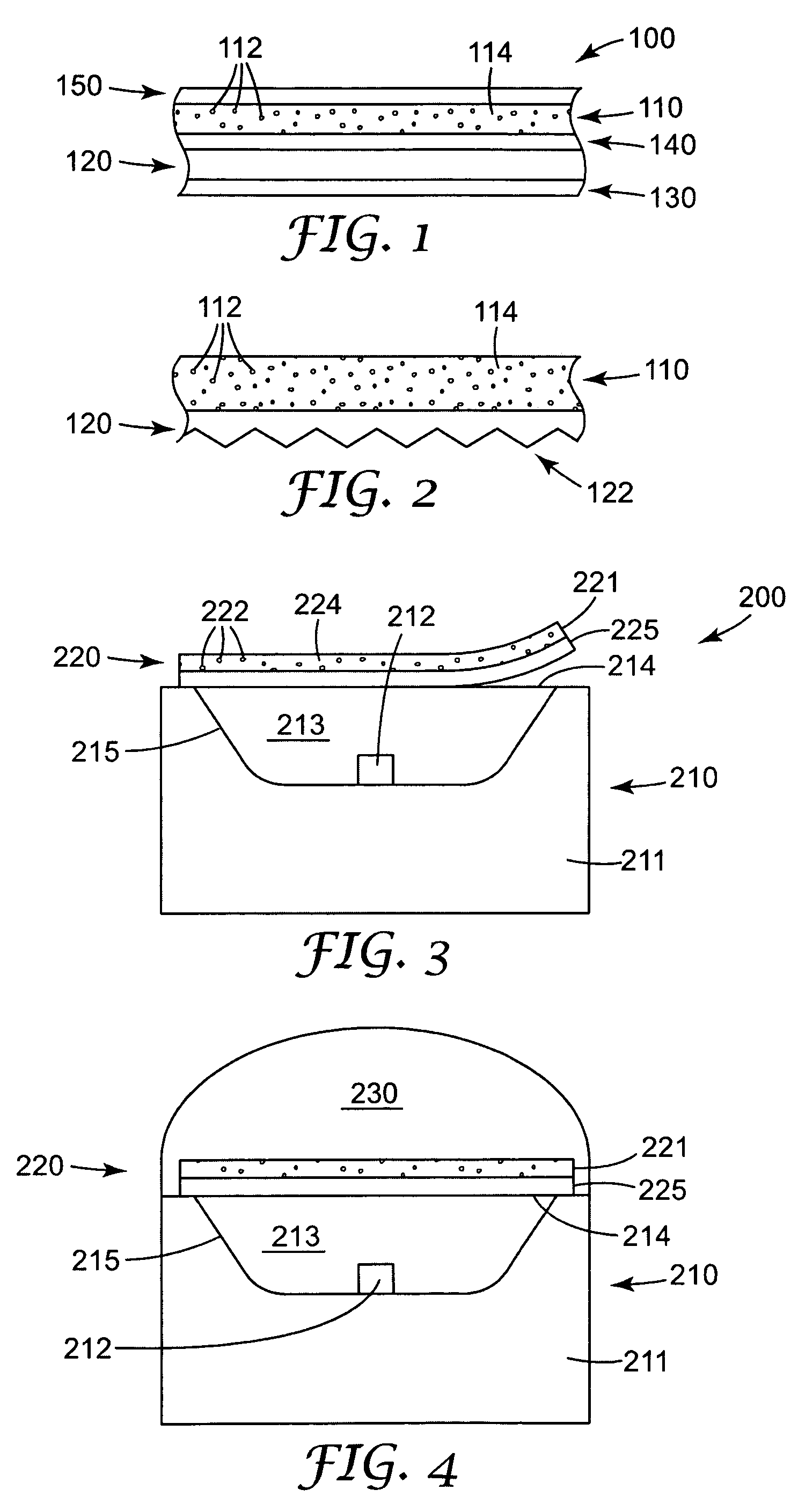
[0050]A sample of phosphor tape was made by applying a pressure sensitive adhesive to a phosphor-loaded film layer. The phosphor-loaded film layer contained cerium-doped yttrium aluminate (YAG:Ce) phosphor in a UV-curable binder. The phosphor-loaded film was made from a paste prepared by hand mixing 13.63 grams of YAG:Ce phosphor (designated QMK58 / F-U1 by Phosphor Technology, Ltd. of Stevenage, England) into 20.45 grams of UV-curable resin (designated NOA 81 by Norland Products, Cranbury, N.J.). The paste was coated onto a sheet of polyethylene terphthalate (PET) by hand using the 100 micrometer gap of a square multiple clearance applicator (designated PAR-05353 by BYK-Gardner USA, Columbia, Md. The wet film was cured by placing it below a bank of UV bulbs (designated F15T8 / 350BL by Osram Sylvania, Danvers, Mass.) for about 5 minutes. A pressure-sensitive adhesive (designated Optically Clear Adhesive (OCA) specifically a cross-linked iso-octyl acrylate / acetic acid (90 / 10)PSA) was co...

example 2

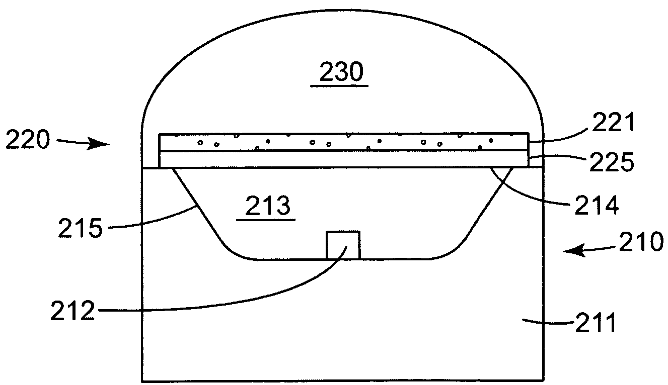
[0051]The phosphor tape prepared in Example 1 was adhered to an encapsulated blue LED (commercially available from Stanley Electric Company, Tokyo, Japan) to produce a white LED. To attach the film, the release liner was removed and the LED top surface was placed against the exposed adhesive. The film was firmly pressed against the encapsulant to ensure that the adhesive touched the encapsulant and had a good optical contact. The film was cut to the size of the LED. The PET substrate was then peeled away from the phosphor-loaded layer, leaving just the phosphor-loaded layer bonded to the LED package by the pressure sensitive adhesive.

[0052]The optical output of the assembled white LED was measured using a spectroradiometer (designated OL 770-LED by Optronic Laboratories, Inc., Orlando, Fla.) fitted with an integrating sphere (designated OL IS-670-LED by Optronic Laboratories, Inc., Orlando, Fla.). The spectroradiometer was calibrated to report the radiant energy entering the integra...


PUM


Abstract

A phosphor tape article includes a phosphor layer having a phosphor and a polymeric binder material, a pressure sensitive adhesive layer disposed adjacent the phosphor layer such that light transmitted through the pressure sensitive adhesive layer is received by the phosphor layer, and a release liner disposed on the pressure sensitive adhesive layer. The pressure sensitive adhesive layer is disposed between the release liner and the phosphor layer. The phosphor is suitable for excitation by UV or blue LED light, and the phosphor emission has a characteristic decay rate of less than 1 second. Light emitting devices including pieces of phosphor tape, and methods of making such devices, are also disclosed.

Description

BACKGROUND[0001]The present application relates to phosphor tape articles and specifically to phosphor tape articles that include a pressure sensitive adhesive layer.[0002]Many white light sources that utilize LEDs in their construction can have two basic configurations. In one, referred to herein as direct emissive LEDs, white light is generated by direct emission of different colored LEDs. Examples include a combination of a red LED, a green LED, and a blue LED, and a combination of a blue LED and a yellow LED. In another basic configuration, referred to herein as LED-excited phosphor LEDs, a single LED generates a beam in a narrow range of wavelengths, which beam impinges upon and excites a phosphor material to produce visible light. The phosphor can include a mixture or combination of distinct phosphor materials, and the light emitted by the phosphor can include a plurality of narrow emission lines distributed over the visible wavelength range such that the emitted light appears...

Claims


Application Information

Patent Timeline
Patent Type & Authority Patents(United States)
IPC IPC(8): H01L31/12H01L21/00H01L33/50
CPCH01L33/507H01L33/44H01L2933/0041H01L33/501H01L31/12
Inventor SCHARDT, CRAIG R.THOMPSON, DAVID SCOTTMEIXNER, LARRY A.LEATHERDALE, CATHERINE A.
Owner 3M INNOVATIVE PROPERTIES CO
Why Eureka
Try Eureka