Spark plug for internal combustion engine

a technology for spark plugs and internal combustion engines, which is applied in spark plugs, basic electric elements, electric devices, etc., can solve the problems of gas tightness decline, gas leakage, and possible decline in gas tightness, so as to prevent the concentration of stress

Inactive Publication Date: 2008-10-02
NGK SPARK PLUG CO LTD
View PDF9 Cites 4 Cited by
  • Summary
  • Abstract
  • Description
  • Claims
  • Application Information

AI Technical Summary

Benefits of technology

[0024]In configuration (7), the annular groove portion 23 has a bottom wall portion 24 including the minimum-diameter portion and a tapered rear wall portion 25 formed continuously from a rear end side of the bottom wall portion 24. Here, if an angle formed by the bottom wall portion and the rear wall portion becomes close to a right angle, stress is concentrated on a boundary between the bottom wall portion 25 and the rear wall portion 24, so that there is a possibility that cracking occurs at that boundary or in the vicinity thereof. In contrast, according to this configuration, in the cross-section including the axis C1 of the insulator 2, an angle formed by an extension line of an outer configuration line 24a of the bottom wall portion 24 and an outer configuration line 25a of the tapered rear wall portion 25 is set to less than or equal to 40 degrees. This makes it possible to prevent the concentration of stress at the boundary between the bottom wall portion and the rear wall portion and prevent a situation in which the insulator cracks due to provision of the annular groove portion. In the case where the glazing layer is provided on the annular groove portion, the angle formed by an extension line of an outer configuration line of the glazing layer surface covering the bottom wall portion and an outer configuration line of the glazing layer surface covering the rear wall portion is set to less than or equal to 40 degrees.

Problems solved by technology

If an engagement allowance of the crimped portion with respect to a rear end of the large-diameter portion is insufficient, a gap is likely to occur between the insulator and the metal shell.
Consequently, the force with which the insulator is held by the crimped portion declines, possibly leading to a decline in gas-tightness.
In addition, as the engagement allowance decreases, the holding force of the crimped portion declines, with the result that stability of the tightened state of the insulator with respect to the metal shell can possibly decline.
However, adoption of either method leads to a decline in the strength of the spark plug, and there is a possibility that the spark plug cannot withstand the aforementioned harsh environment of the interior of the combustion chamber.

Method used


Image

  • Spark plug for internal combustion engine
  • Spark plug for internal combustion engine
  • Spark plug for internal combustion engine

Examples


Embodiment Construction

[0037]Hereafter, a description will be given of an embodiment of the invention with reference to the drawings. However, the present invention should not be construed as being limited thereto.

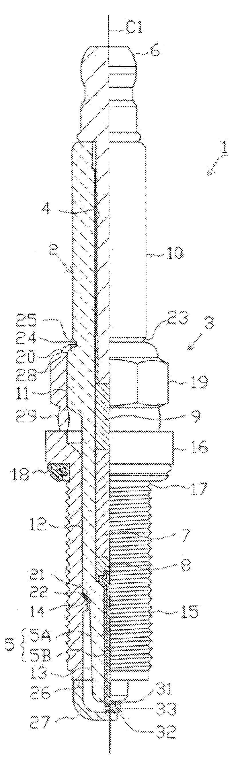
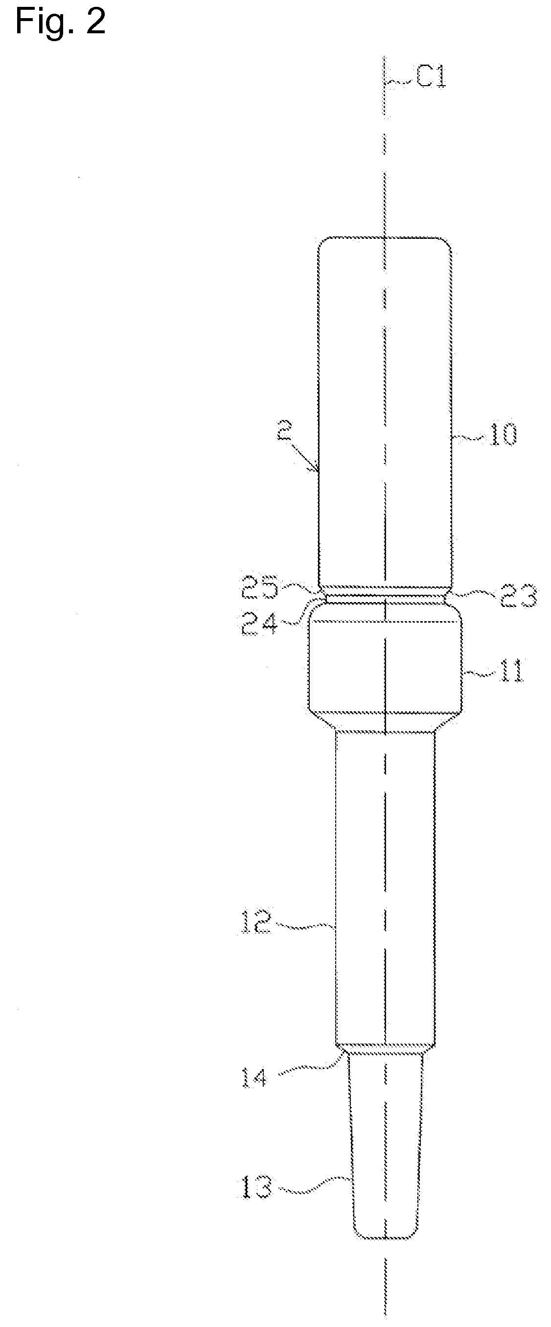
[0038]FIG. 1 is a fragmentary front elevational view illustrating a spark plug 1. In FIG. 1, the direction of an axis C1 of the spark plug 1 is a vertical direction in the drawing, the lower side of the drawing is a leading end side of the spark plug 1, and the upper side is a rear end side thereof.

[0039]The spark plug 1 is comprised of a cylindrical insulator 2, a cylindrical metal shell 3 for holding it, and the like.

[0040]An axial hole 4 is penetratingly formed in the insulator 2 along the axis C1. A center electrode 5 is inserted and fixed in a leading end portion side of the axial hole 4, and a terminal electrode 6 is inserted and fixed in a rear end portion side thereof. A resistor 7 is disposed between the center electrode 5 and the terminal electrode 6 inside the axial hole 4, and opposi...


PUM


Abstract

A spark plug (1) for an internal combustion engine includes: a cylindrical insulator (2) having an axial hole (4) penetrating in a direction of an axis (C1); a center electrode (5) partially inserted in the axial hole (4); a metal shell (3) surrounding an outer periphery of the insulator (2) and which is fixed to the insulator (2) by means of a crimped portion (20) provided at a rear end portion of the metal shell (3); and a ground electrode (27) joined to the metal shell (3) such that a portion of the ground electrode (27) opposes a leading end portion of the center electrode (5) via a spark discharge gap (33), wherein the insulator (2) has an annular groove portion (23) which opposes an inner edge of the crimped portion (20).

Description

BACKGROUND OF THE INVENTION[0001]1. Field of the Invention[0002]The present invention relates to a spark plug for an internal combustion engine.[0003]2. Description of the Related Art[0004]A spark plug for an internal combustion engine is installed in an internal combustion engine of an automobile or the like and is used for igniting an air-fuel mixture. The spark plug generally comprises a center electrode, an insulator provided on the outer side of the center electrode, and a cylindrical metal shell provided on the outer side of the insulator. In addition, the insulator has a rear end-side trunk portion formed on its rear end side, a large-diameter portion formed on a leading end side of the rear end-side trunk portion, and an intermediate trunk portion and a long leg portion formed on a leading end side of the large-diameter portion. The insulator and the metal shell are combined, for example, in a state in which the insulator is inserted in the metal shell, a rear end portion of...

Claims


Application Information

Patent Timeline
Patent Type & Authority Applications(United States)
IPC IPC(8): H01T13/36
CPCH01T13/36
Inventor MORIBE, MAISUZUKI, AKIRA
Owner NGK SPARK PLUG CO LTD
Why Eureka
Try Eureka