Display device and electronic apparatus

a technology of electronic equipment and display device, which is applied in the field of display device and electronic equipment, can solve the problems of difficult to distinguish the detection light that is reflected by the pointing object from external light, become practically impossible, and difficult to detect the position of a finger with a high precision, and achieve the effect of high precision

Inactive Publication Date: 2008-10-23
SEIKO EPSON CORP
View PDF8 Cites 77 Cited by
  • Summary
  • Abstract
  • Description
  • Claims
  • Application Information

AI Technical Summary

Benefits of technology

[0011]An advantage of some aspects of the invention is to provide a display device such as a liquid crystal device that is capable of identifying the position of pointing means such as a finger, though not limited thereto, with a high prec

Problems solved by technology

However, the related-art display device that is disclosed in JP-A-2004-318819 or JP-A-2006-238053 has not addressed a technical problem of a difficulty in detecting the position of a pointing object with a high precision under a certain light condition.
Specifically, in the configuration of a display device that is disclosed in these patent publications, since the level of an electric current for detection that flows through an optical sensor is weak, it could become practically impossible, or at best difficult, to detect the position of a pointing object such as a finger with a high precision depending on a change, variation, or fluctuation in the optical intensity of outside light that irradiates the display surface.
In

Method used


Image

  • Display device and electronic apparatus
  • Display device and electronic apparatus
  • Display device and electronic apparatus

Examples


Embodiment Construction

[0053]With reference to accompanying drawings, exemplary embodiments of a display device and an electronic apparatus according to some aspects of the invention are explained below.

1: Display Device

1-1: General Configuration of Display Device

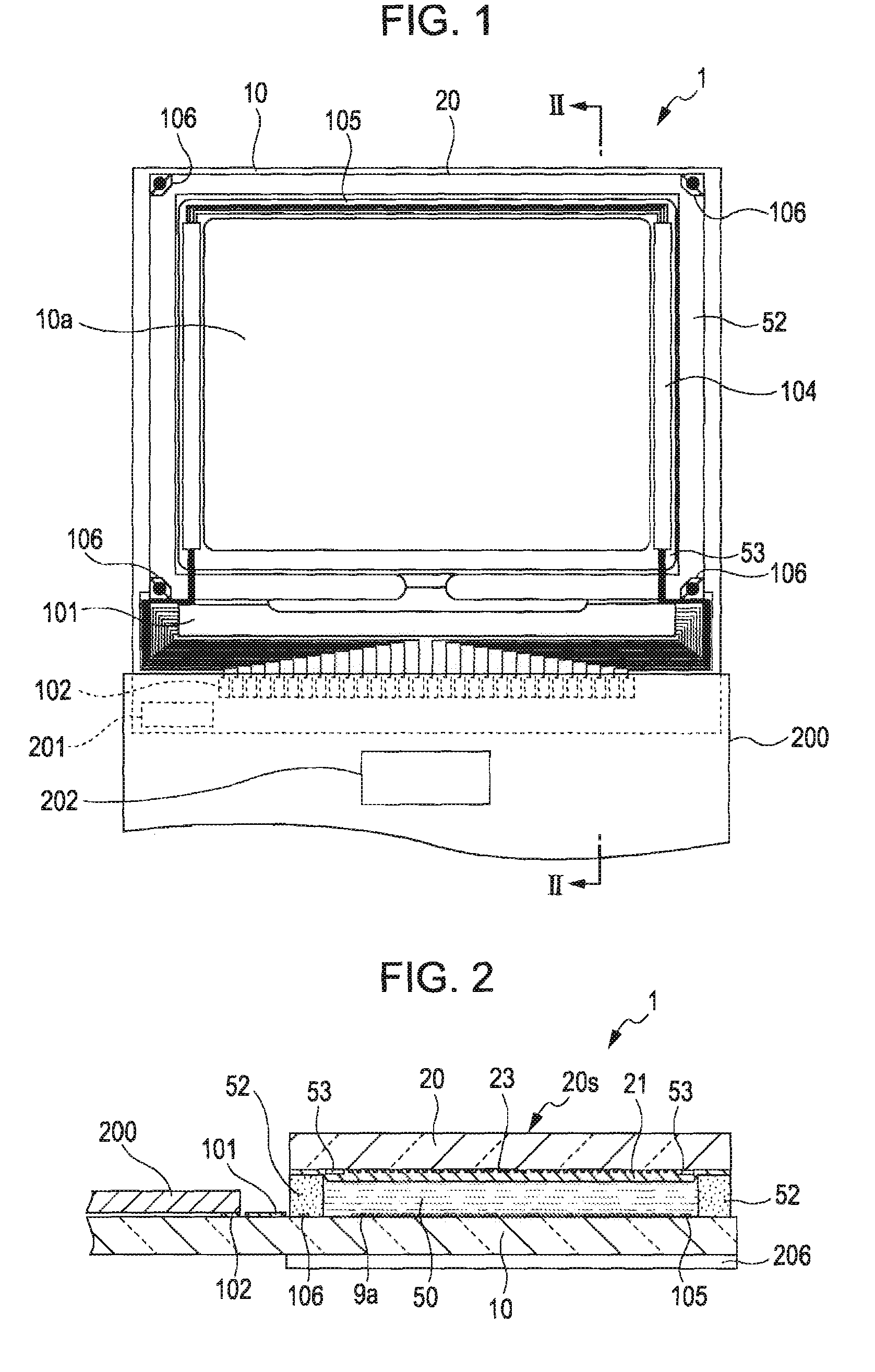
[0054]First of all, with reference to FIGS. 1 and 2, an explanation is given below of the general configuration of a liquid crystal device 1, which is an exemplary embodiment of a “display device” according to the invention. FIG. 1 is a plan view of the liquid crystal device 1 that schematically illustrates an example of the configuration of a TFT array substrate and various components formed or deposited thereon, which are viewed in combination from a certain point at the counter-substrate side. FIG. 2 is a cross sectional view taken along the line II-II of FIG. 1. The liquid crystal device 1 according to the present embodiment of the invention is provided with a built-in driving circuit. The liquid crystal device 1 according to the present embo...


PUM


Abstract

The invention provides a display device including: a light source that emits a plurality of light-source lights having intensities different from one another at points in time different from one another from a back side opposite a display surface that is pointed by pointing means toward the display surface; a detecting unit that is provided at the back side and functions to detect a plurality of reflected lights, which are obtained as a result of reflection of the plurality of light-source lights by the pointing means; and an identifying unit that identifies the position of the pointing means on the basis of each of a plurality of third images by calculating a finite difference value between brightness data of a first image that is generated on the basis of one reflected light among the plurality of reflected lights and brightness data of each of a plurality of second images that is generated on the basis of a plurality of other reflected lights among the plurality of reflected lights, the above-mentioned plurality of other reflected lights having an intensity that differs from that of the above-mentioned one reflected light, and then by generating each of the plurality of third images on the basis of the corresponding one of the plurality of calculated finite difference values.

Description

BACKGROUND[0001]1. Technical Field[0002]The present invention generally relates to the technical field of a display device. More particularly, the invention relates to a display device having an input sensing function such as a touch-panel-type liquid crystal device. In addition, the invention further relates to an electronic apparatus that is provided with such a display device.[0003]2. Related Art[0004]In the technical field pertaining to the invention, a variety of display devices having a so-called touch panel input function has been proposed so far. In the configuration of a touch-panel-type liquid crystal device, which is an example of such a display device having a touch panel input function, an optical sensor (i.e., light sensor, photo sensor) is provided for either each of a plurality of pixel units or each of a plurality of groups of pixel units, where each group thereof is made up of a given number of pixel units. With such a configuration, in addition to its basic functi...

Claims


Application Information

Patent Timeline
IPC IPC(8): G06F3/042
CPCG06F3/0412G06F3/042
Inventor OTA, HITOSHI
Owner SEIKO EPSON CORP
Why Eureka
Try Eureka