[0012]A need exists for a shielding needle
assembly that achieves secure and effective shielding of a used needle cannula, and which is simple to manufacture and easy to operate. Additionally, a need exists for a needle
assembly, such as for use in a blood collection set, that is passively operated during a
normal blood collection procedure.
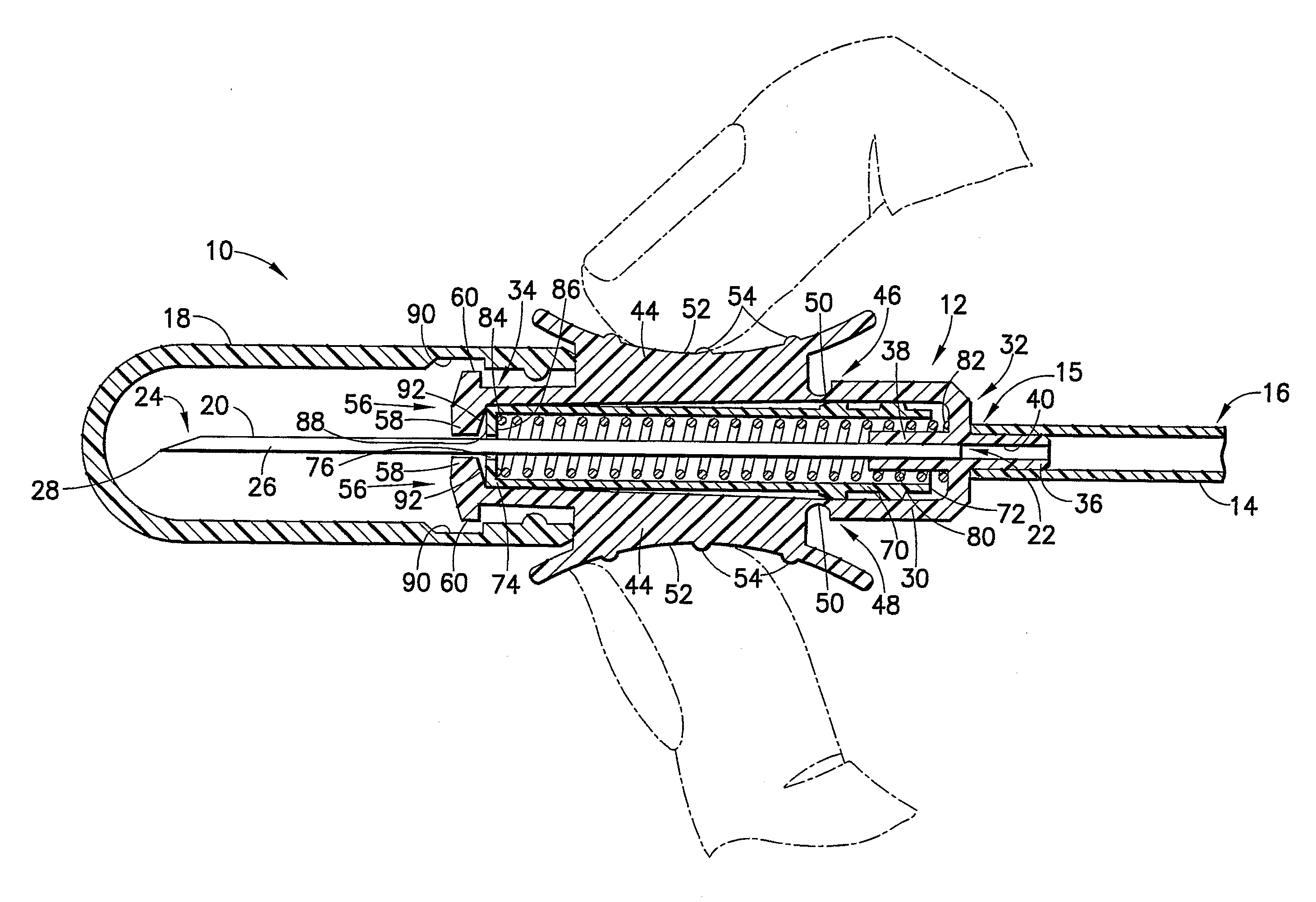
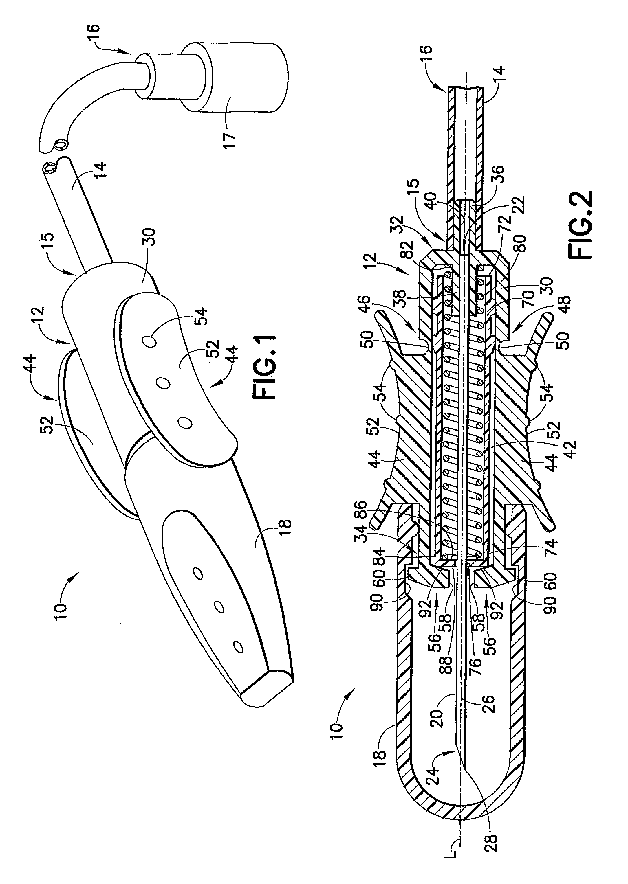
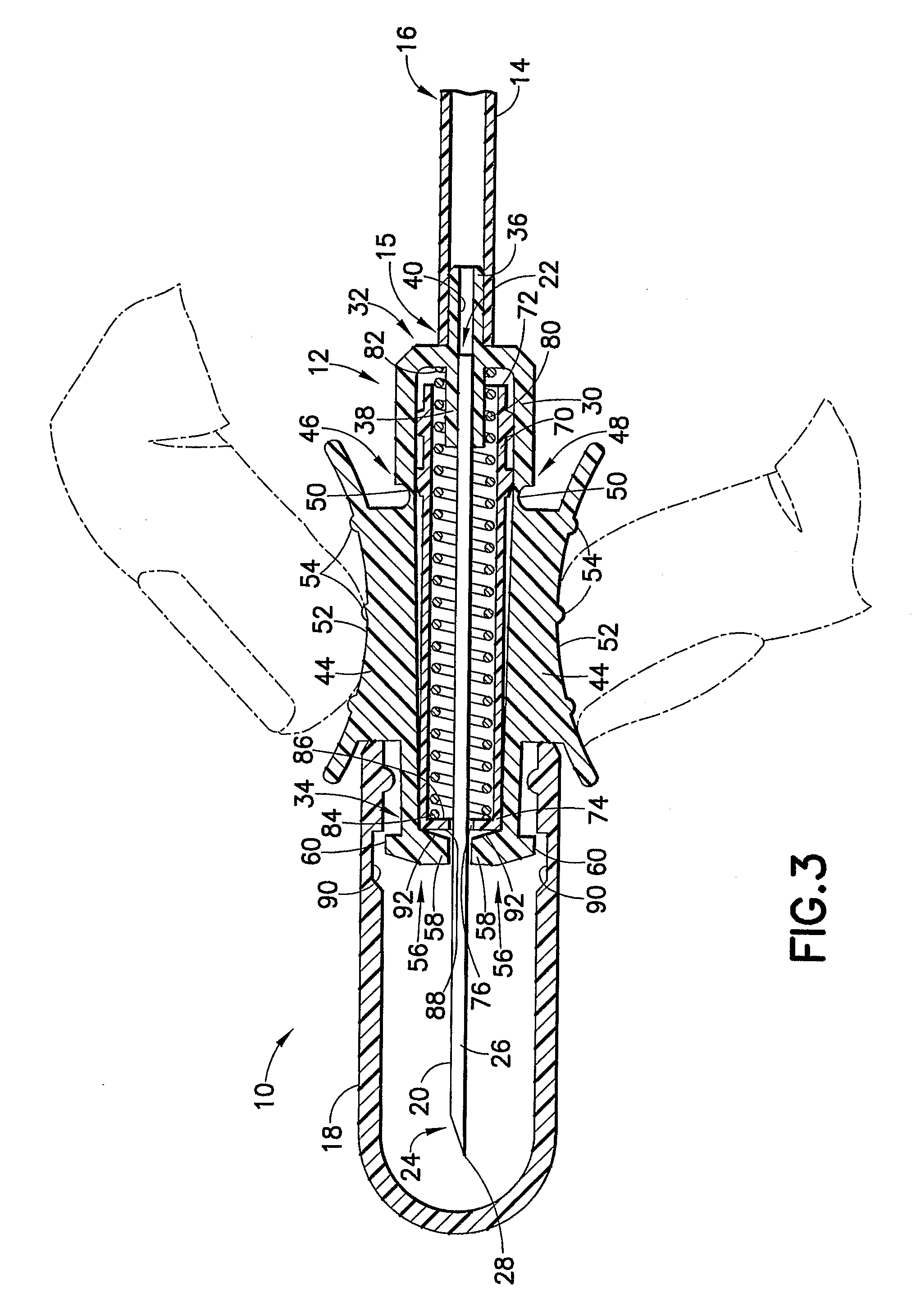
[0013]In one embodiment of the present invention, a safety needle device comprises a hub including a passageway extending therethrough and a needle cannula having a puncture tip extending from a forward end thereof. A shield member is in telescoping association with the hub, with at least one of the hub and the shield member adapted for relative telescoping movement with respect to the other between a first position in which the puncture tip of the needle cannula is exposed from a forward end of the shield member and a second position in which the puncture tip of the needle cannula is encompassed within the shield member. A drive member is disposed between the hub and the shield member, and is capable of biasing the hub and the shield member telescopically away from each other.
External pressure applied by a user to at least one of the hub and the shield member provides an engagement therebetween, preventing the drive member from biasing the hub and the shield member away from each other, such as in an axial direction. For example,
external pressure applied by a user between corresponding surfaces of the hub and the shield member may provide an interference engagement therebetween, preventing the drive member from biasing the hub and / or the shield member axially away from each other.
[0014]In one embodiment, the safety needle device further includes a releasable packaging cover disposed about the puncture tip of the needle cannula. The packaging cover is adapted to apply external pressure to at least one of the hub and the shield member to provide an engagement therebetween, thereby preventing the drive member from biasing the hub and the shield member axially away from each other. In this manner, application of external pressure by a user to at least one of the hub and the shield member allows for release of the packaging cover from the needle device, and maintains the engagement between the hub and the shield member to prevent the drive member from biasing the hub and the shield member axially away from each other, thus providing a passive device.
[0016]In a further embodiment, a safety needle device comprises a needle cannula comprising a proximal end and a distal end with a puncture tip, a housing defining a passageway extending therethrough, with the puncture tip of the needle cannula extending from a distal end of the housing, and a packaging cover releasably disposed about the distal end of the housing and enclosing the puncture tip of the needle cannula prior to using the safety needle device. The housing comprises at least one release member disposed at least partially within the packaging cover and adapted to flex radially inward toward a central longitudinal axis of the housing upon applying external pressure thereto, allowing passive release of the packaging cover from the distal end of the housing. The at least one release member may be pivotally connected to the housing, and may include a locking tab engaging a locking groove defined within the packaging cover. In this manner, application of external pressure causes the locking tab to disengage from the locking groove to allow passive release of the packaging cover from the distal end of the housing. Desirably, the housing includes a pair of opposing release members each comprising a locking tab engaging a locking groove defined within the packaging cover. A shield member may further be provided, which is axially movable with respect to the housing and which is maintained in a retracted position against a biasing force between the housing and the shield member by external pressure applied to the release member by the packaging cover, which external pressure maintains the shield member in the retracted position in which the puncture tip of the needle cannula is exposed from the shield member. Application of external pressure to the at least one release member, such as through a user's fingers grasping the at least one release member, causes the packaging cover to release from the housing and further causes the at least one release member to continue to maintain the shield member in the retracted position against the bias. The safety needle device may further be connected to a flexible tube which is adapted for connection to a receptacle, thereby providing a blood collection assembly.
[0019]In yet a further particular embodiment, the hub includes a dorsal member extending from an external surface thereof, and the shield member includes a grip structure extending dorsally therefrom adapted for corresponding engagement with the dorsal member at the external surface of the hub when the shield member is in a first retracted position, thereby forming a dorsal grasping structure.
External pressure applied between the grip structure of the shield member and the dorsal member of the hub prevents the drive member from biasing the hub and the shield member axially away from each other. In such an embodiment, the shield member preferably telescopes within the passageway of the hub and the grip structure extends dorsally from the shield member toward the dorsal member of the hub, such that external pressure applied between the grip structure of the shield member and the dorsal member of the hub establishes frictional engagement therebetween. The shield member is thereby maintained in a retracted position within the passageway of the hub against the bias of the drive member with the puncture tip of the needle cannula exposed. Release of the external pressure between the grip structure of the shield member and the dorsal member of the housing releases the frictional engagement, allowing the drive member to bias the shield member toward an extended position in which the puncture tip of the needle cannula is encompassed within the shield member. A packaging cover may be provided in such an embodiment for releasably covering the forward end of the puncture tip when the shield is in the retracted position. Such a protective cap may provide for external pressure between the grip structure of the shield and the dorsal member of the housing to maintain the shield in the retracted position against the bias of the drive member.

