Flash Activated Passive Shielding Needle Assembly

a passive shielding and flash activated technology, applied in the field of blood collection sets, can solve the problems of complex arrangement, high manufacturing and assembly costs, and expose the user to potential needle-stick wounds, and achieve the effects of secure and effective shielding, simple and inexpensive manufacturing, and convenient operation

Active Publication Date: 2009-10-15
BECTON DICKINSON & CO
View PDF6 Cites 109 Cited by
  • Summary
  • Abstract
  • Description
  • Claims
  • Application Information

AI Technical Summary

Benefits of technology

[0011]A need exists for a blood collection set including a shielding needle assembly that achieves secure and effective shielding of a used needle cannula, and which is simple and inexpensive to manufacture and easy to operate. An additional need exists for a blood collection set with a passively operated shielding mechanism that allows a healthcare professional to probe for a vein without activating the shielding mechanism.

Problems solved by technology

This results in complex arrangements that are costly to manufacture and assemble.
Additionally, operation of the needle assemblies to move the tip guard into the proper position over the pointed distal end of the needle cannula requires substantial manual manipulation by the user of the device, exposing the user to potential needle-stick wounds.

Method used


Image

  • Flash Activated Passive Shielding Needle Assembly
  • Flash Activated Passive Shielding Needle Assembly
  • Flash Activated Passive Shielding Needle Assembly

Examples


Embodiment Construction

[0028]For purposes of the description hereinafter, the words “upper”, “lower”, “right”, “left”, “vertical”, “horizontal”, “top”, “bottom”, “lateral”, “longitudinal” and like spatial terms, if used, shall relate to the described embodiments as oriented in the drawing figures. However, it is to be understood that many alternative variations and embodiments may be assumed except where expressly specified to the contrary. It is also to be understood that the specific devices and embodiments illustrated in the accompanying drawings and described herein are simply exemplary embodiments of the invention.

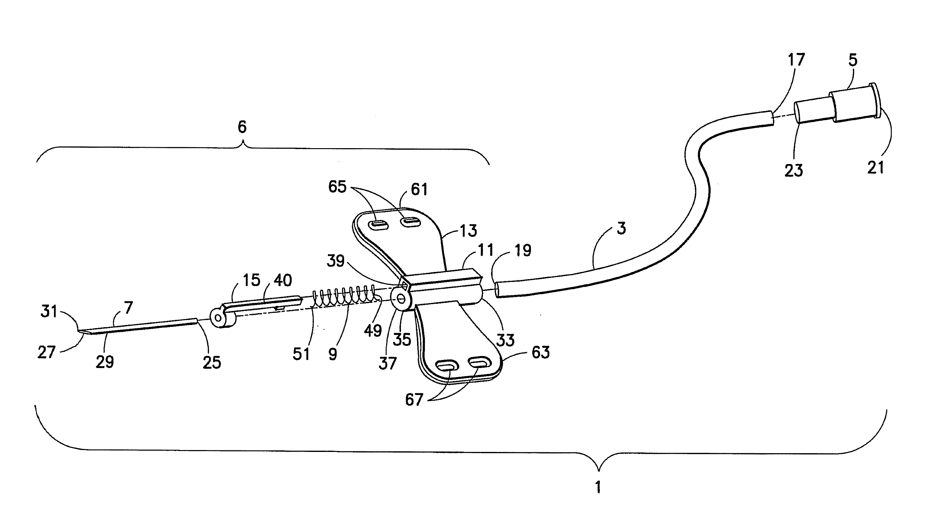
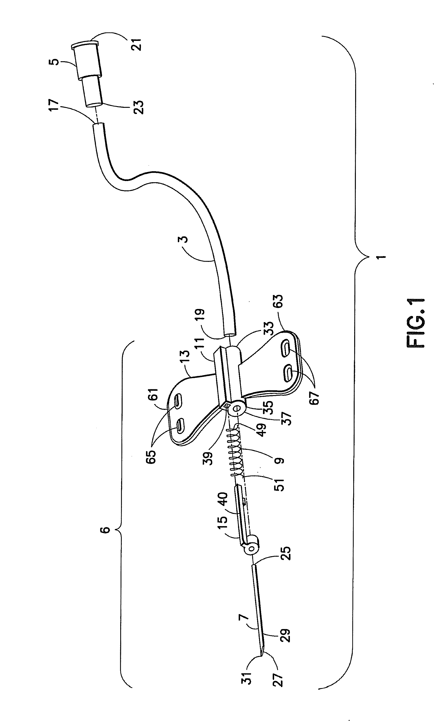
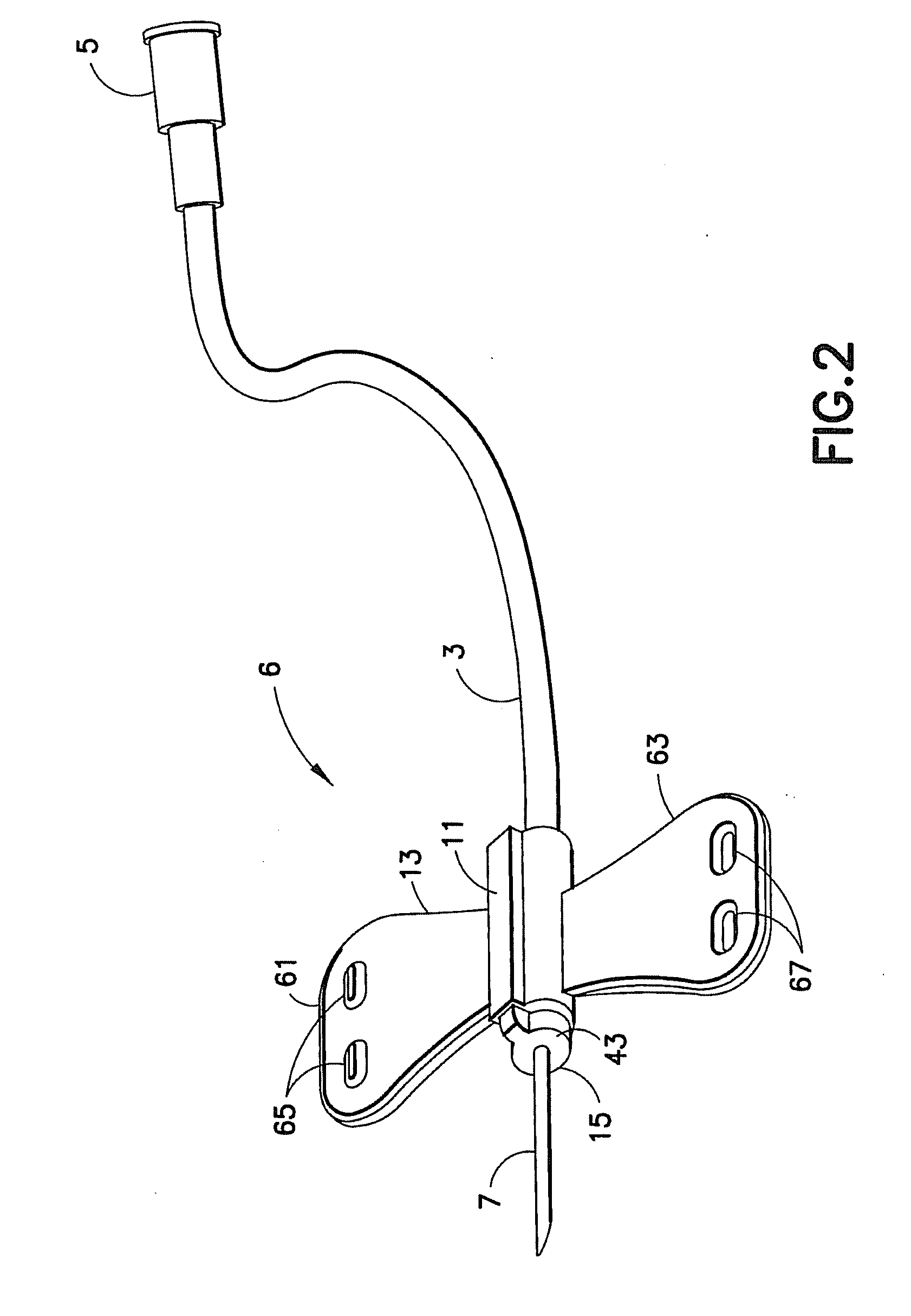
[0029]Generally, an embodiment of the invention relates to a passively activated shieldable needle assembly. Passive activation of the safety features of the present device is accomplished during normal operation of the assembly in connection with a standard medical procedure, without the need for any other conscious action by the health care professional. The shielding feature of the assem...


PUM


Abstract

A safety needle device includes a housing including a passageway with a needle cannula extending therefrom. A shielding member is movable between a first position in which a puncture tip of the needle cannula is exposed therefrom and a second position in which the puncture tip of the needle cannula is encompassed therein. The shielding member is maintained in the first position against a biasing force which biases the shielding member toward the second position. A fluid and/or temperature activation material, such as a hydrogel or a compressed sponge, is associated with the shielding member and is adapted to deform upon contact with a fluid medium and/or a certain temperature or temperature range. Fluid flowing through the needle cannula, such as blood flow during a blood collection procedure, causes the activation material to deform, such as through expansion, thereby releasing the shielding member from the first position and allowing the drive member to bias the shielding member toward the second position.

Description

BACKGROUND OF THE INVENTION[0001]1. Field of the Invention[0002]The present invention relates to blood collection sets for safe and convenient handling of needles used in blood collection procedures. More particularly, the present invention relates to a blood collection set including a safety shield for protecting users from a used needle tip.[0003]2. Description of Related Art[0004]Disposable medical devices having medical needles are used for administering medication or withdrawing fluid from the body of a patient. Such disposable medical devices typically include blood-collecting needles, fluid handling needles, and assemblies thereof. Current medical practice requires that fluid containers and medical needles used in such devices be inexpensive and readily disposable. Existing blood collection devices often employ some form of durable, reusable holder on which detachable and disposable medical needles and fluid collection tubes may be mounted. A blood collection device of this n...

Claims


Application Information

Patent Timeline
Patent Type & Authority Applications(United States)
IPC IPC(8): A61M5/32
CPCA61B5/1405A61B5/153A61M25/0637A61M5/3269A61M25/0625A61M5/326A61B5/15003A61B5/150259A61B5/150389A61B5/150519A61B5/150648A61B5/150717A61B5/15074A61B5/150786A61B5/1535A61B5/14A61B5/1411A61B5/15A61B5/150374A61B5/150534A61B5/150633A61M5/158A61M5/162A61M5/1626A61M5/3205A61M5/321A61M5/3243A61M5/3293A61M25/0084A61M25/0097A61M25/0612A61M25/0618A61M2005/3252A61M2025/0042A61M2025/0089A61M2202/0413A61M2205/273A61M2210/04A61M2210/12
Inventor HWANG, CHARLES G.WILKINSON, BRADLEY M.
Owner BECTON DICKINSON & CO
Why Eureka
Try Eureka