U-turn bus bar

a bus bar and u-turn technology, applied in the field of bus bars, can solve problems such as difficult bending and manufacturing, and achieve the effects of reducing manufacturing difficulty, reducing manufacturing difficulty, and ensuring safety

Inactive Publication Date: 2008-12-18
DENSO CORP
View PDF8 Cites 16 Cited by
  • Summary
  • Abstract
  • Description
  • Claims
  • Application Information

AI Technical Summary

Benefits of technology

[0009]The object of this invention is to solve the problem described above and provide a bus bar capable of ensuring sufficient conductivity, heat radiation efficiency, and easiness in manufacturing.

Problems solved by technology

Therefore, there is a problem that the volume per unit length is increased, which means that a plate to be punched may become bulky, and at the same time increasing the geometrical moment of inertia, resulting in difficulty in bending and manufacturing.

Method used


Image

  • U-turn bus bar
  • U-turn bus bar
  • U-turn bus bar

Examples


Embodiment Construction

[0032]An embodiment of the invention will be explained below with reference to FIGS. 1 and 2.

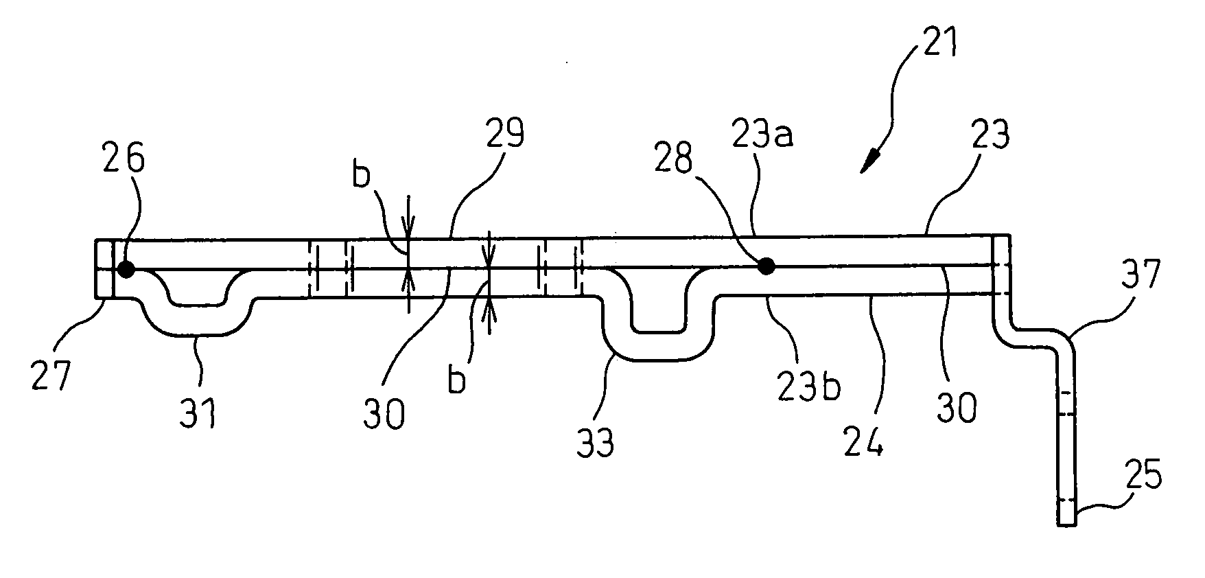
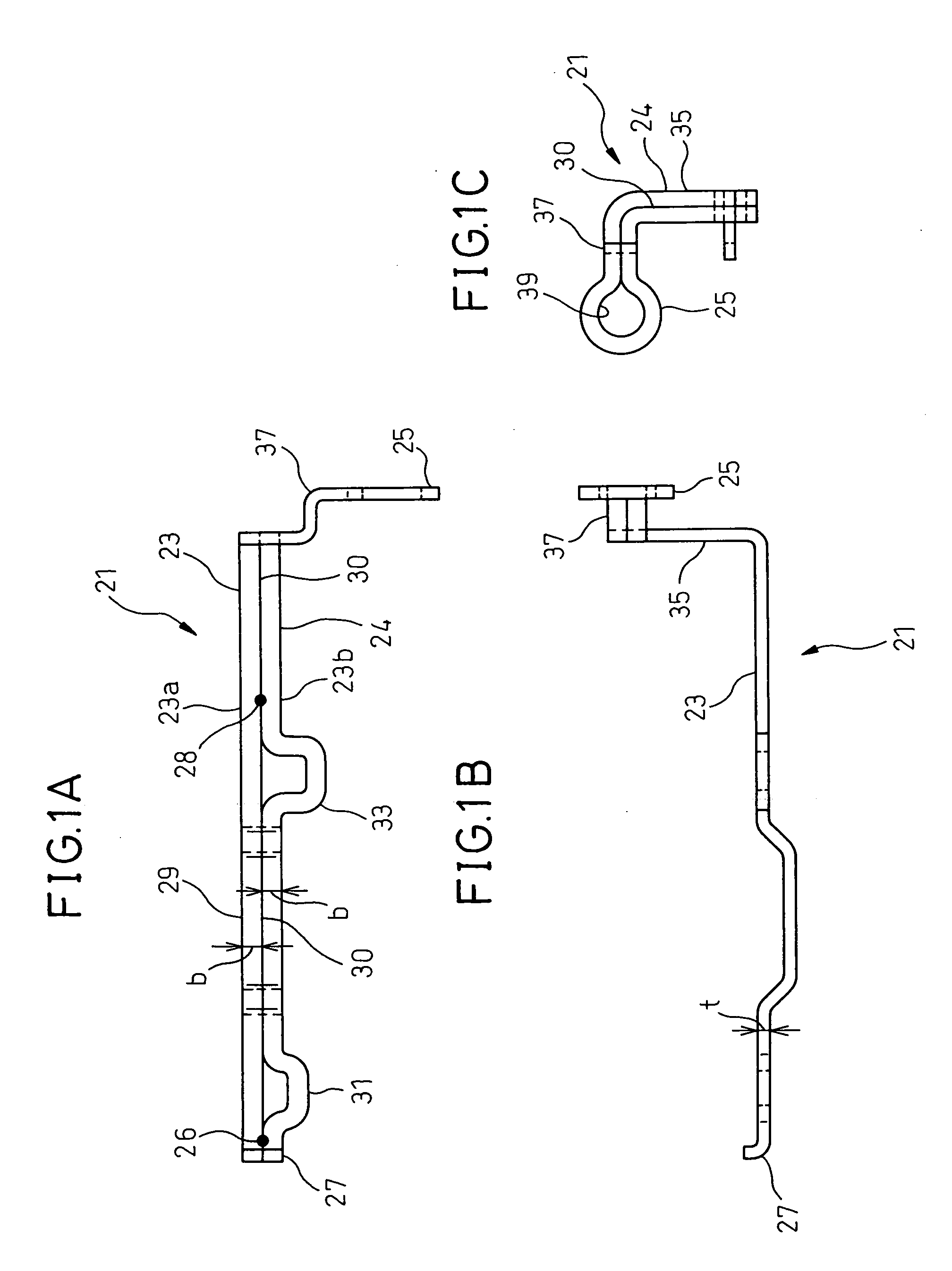
[0033]In FIG. 1, numeral 21 designates a U-turn bus bar according to an embodiment of the invention. U-turn bus bar 21 is configured by bending a linear square member 23 of a conductive material with width b and thickness t in U-shape. Bus bar 21 has first square member 23a on one side and second square member 23b on the other side.

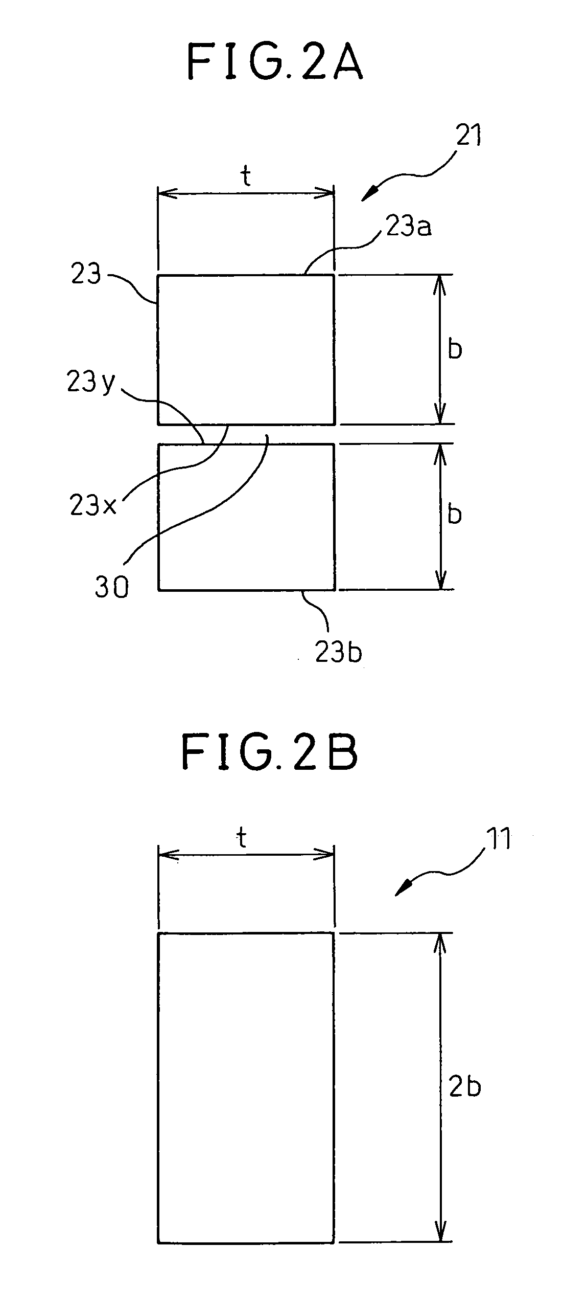
[0034]First and second square members 23a, 23b are coupled to each other at U-turn bend 25 and formed in a parallel state as parallel portion 24. End portions 27 opposing to U-turn bend 25 are welded at spot-welding portion 26 by spot-welding. Another spot-welding portion 28 is formed by spot-welding at parallel portion 24. There is gap 30 between first square member 23a and second square member 23b except the spot-welding portions 26, 28. In this way, as shown in FIG. 2A, bus bar 21 has thickness t and width 2b as a whole.

[0035]This bus bar 21 has substantially l...


PUM


Abstract

A U-turn bus bar comprises a body portion constituting a linear essential part formed of a conductive plate member, having an overall thickness (t) and an overall width (2b); at least a terminal portion expanded in the direction perpendicular to the longitudinal direction of the body portion; and a connection hole formed at one end of the body portion. The body portion includes a U-turn bend formed by bending the body portion into a U-turn shape.

Description

BACKGROUND OF THE INVENTION[0001]1. Field of the Invention[0002]This invention relates to a bus bar used in a circuit inside an electrical connection box, etc., of an automotive vehicle.[0003]2. Description of the Related Art[0004]In recent years, a bus bar has been used as a power terminal of an inverter in a hybrid car. For example, bus bar 11 shown in FIG. 3, has an essential part with a thickness t and width 2b as shown in FIG. 2B, which determines an allowable current therein. Bus bar 11 is manufactured in a predetermined shape by punching a plate into a blank with thickness t and width 2b and bending it.[0005]Bus bar 11 includes body portion 13 which is the essential linear part, as a current conductor. Body portion 13 has wide terminal portion 15 expanded in the horizontal direction perpendicular to the longitudinal direction, in order to be connected to an electric wire, etc. One end of body portion 13 has multiple bends and formed with connection hole 17, which is connected...

Claims


Application Information

Patent Timeline
Patent Type & Authority Applications(United States)
IPC IPC(8): H02G5/00
CPCH02G5/02
Inventor OKUSHITA, DAISUKEKONDO, FUMIO
Owner DENSO CORP
Why Eureka
Try Eureka