Computer network connector

Active Publication Date: 2009-01-29
LEGRAND SNC
View PDF11 Cites 12 Cited by
  • Summary
  • Abstract
  • Description
  • Claims
  • Application Information

AI Technical Summary

Benefits of technology

[0024]Thanks to each of these features, the free movement of these three portions towards the rear when the insert rotates is reflected in sliding of the area of con

Problems solved by technology

The limitations of this solution are that the compensation achieved between the crossover and the printed circuit (if the insert is pushed onto or soldered to a circuit) is not of optimum efficacy because compensation is effected in air, which entails conforming to standard isol

Method used


Image

  • Computer network connector
  • Computer network connector
  • Computer network connector

Examples


Embodiment Construction

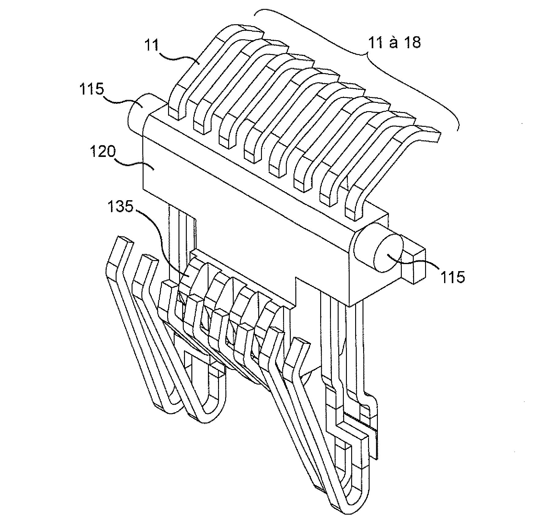
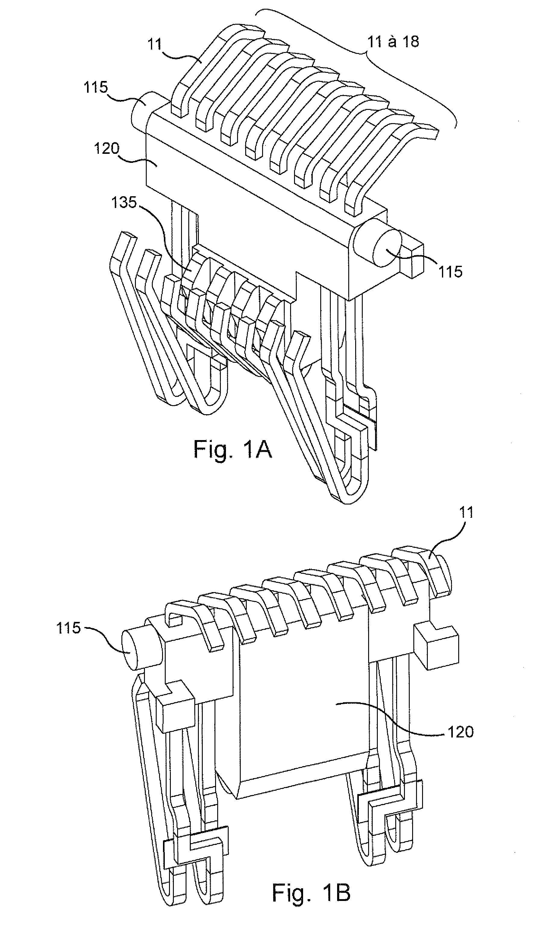
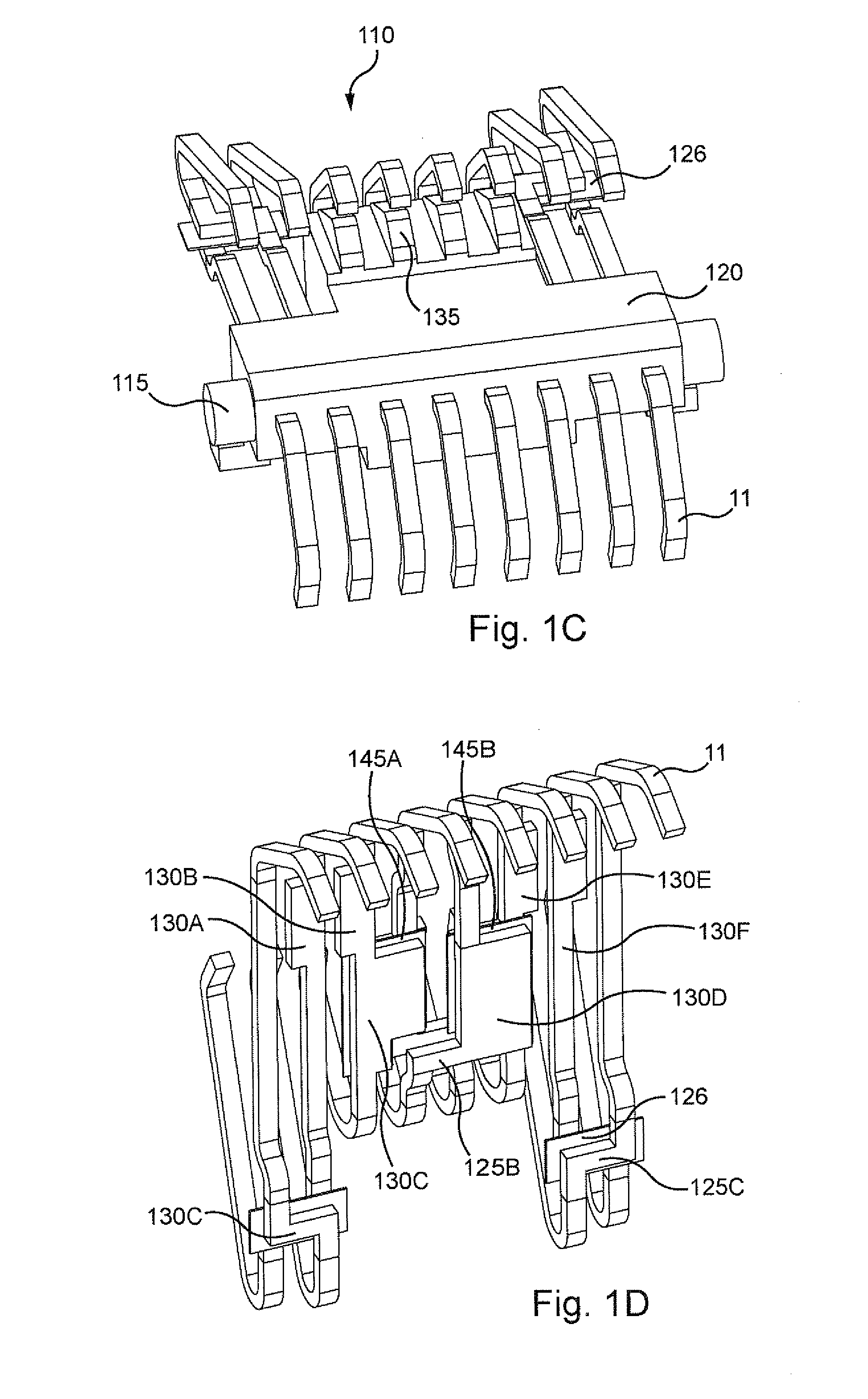
[0034]As explained above, the present invention applies in particular to RJ45 connectors with eight contacts used for computer networks and governed by IEC standard 11 801. The description given hereinafter concerns this type of connector. However, the present invention is not limited to this type of connector and, to the contrary, extends to all connectors having contacts and intended to receive a plug having homologous flat contacts. The RJ45 connectors represented in the figures are intended to receive RJ45 plugs and must be able to accept RJ11 plugs with four contacts defined by the standard without damaging the contacts. The tolerances on the dimensions of these plugs being relatively wide, the contacts of the insert of the connector are sufficiently flexible to accept the extreme plugs and sufficiently rigid to ensure a sufficient contact pressure between the contacts of the insert and the flat contacts of the plugs needed for a contact of good quality that is reflected in a l...


PUM


Abstract

A connector includes an insert including contacts having free parts to receive homologous flat contacts of a plug. The insert further includes a rotation axis about which the insert can be rotated and spring means urging the insert toward the position that it assumes when no plug is present. The insert can include, at the sides, long curved contacts and, in a central portion, shorter curved contacts, the points of contact of the contacts of the insert with the flat contacts of a plug being substantially aligned over all the contacts.

Description

BACKGROUND OF THE INVENTION[0001]1. Field of the Invention[0002]The present invention concerns a computer network connector. It applies in particular to RJ45 connectors used for computer networks and covered by the IEC standard 11 801.[0003]2. Description of the Prior Art[0004]RJ45 connectors must be able to accept all RJ45 plugs and sometimes standard RJ11 type plugs without damaging the contacts. Because the tolerances on the dimensions of these plugs are relatively wide, the contacts of the insert of the RJ45 connector must be flexible to accept plugs representing the extremes. However, these contacts must also be sufficiently rigid to provide the necessary contact pressure between the contacts of the insert and the flat contacts of the plugs to obtain a contact of good quality reflected in a low contact resistance.[0005]A number of solutions to this problem are known. A first produces relatively long insert contacts that incorporate crossovers between some contacts to prevent in...

Claims


Application Information

Patent Timeline
IPC IPC(8): H01R24/00
CPCY10S439/941H01R24/64
Inventor JAOUEN, JEAN-MARCREVOL, DIDIERLAROCHE, VINCENTFORATIER, NATHALIE
Owner LEGRAND SNC
Why Eureka
Try Eureka