Paved surface restraint and method of installation

a technology of paving surface and restraint, which is applied in the field of paver and brick edging, and the laying of brick and paving stones, and can solve problems such as complex installation

a technology of paving surface and restraint, which is applied in the field of paver and brick edging, and the laying of brick and paving stones, and can solve problems such as complex installation

US20090038238A1Active Publication Date: 2009-02-12SUREFOOT HARDSCAPE PRODS

Image

  • Paved surface restraint and method of installation
  • Paved surface restraint and method of installation
  • Paved surface restraint and method of installation

Examples


Embodiment Construction

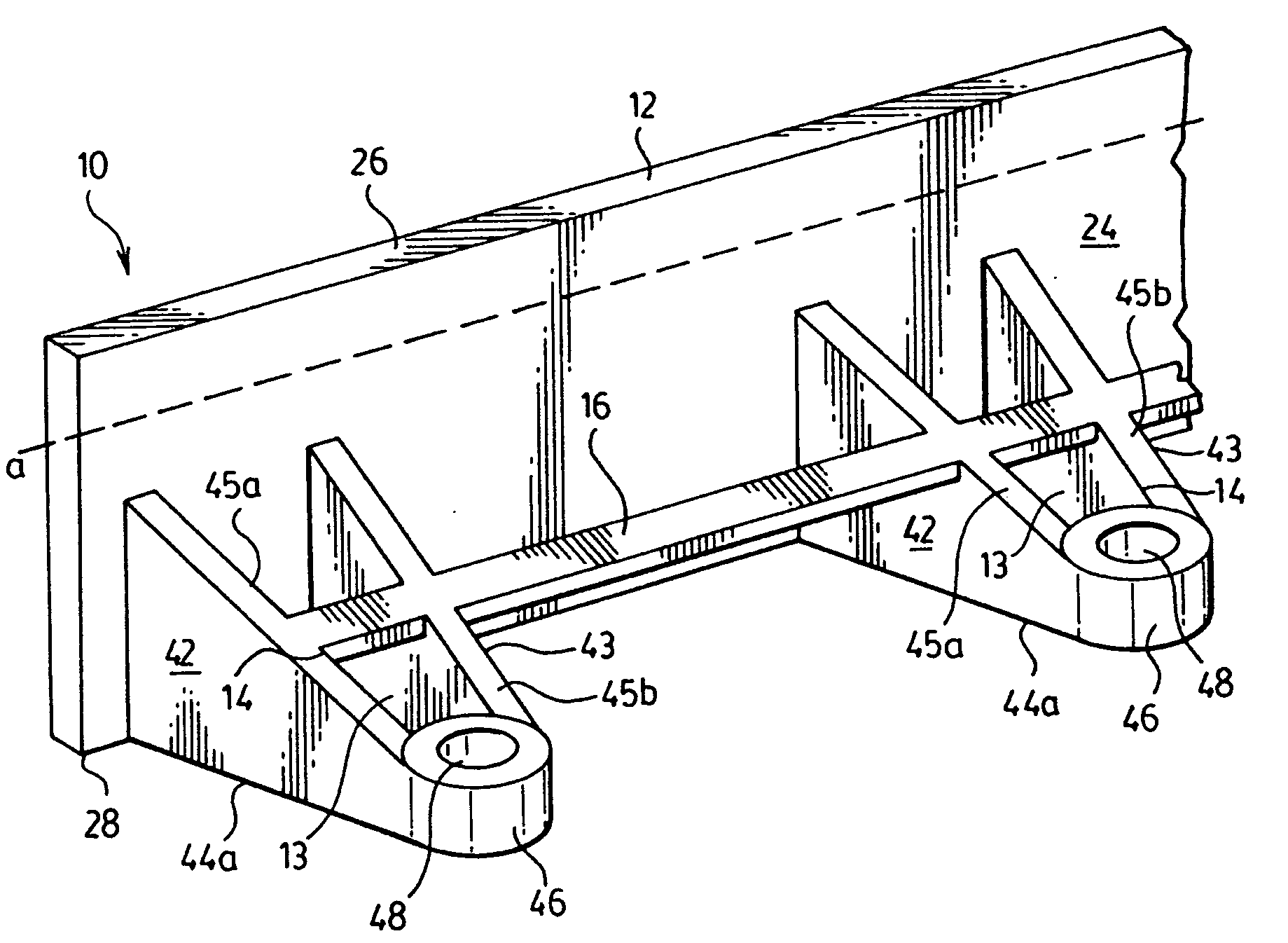
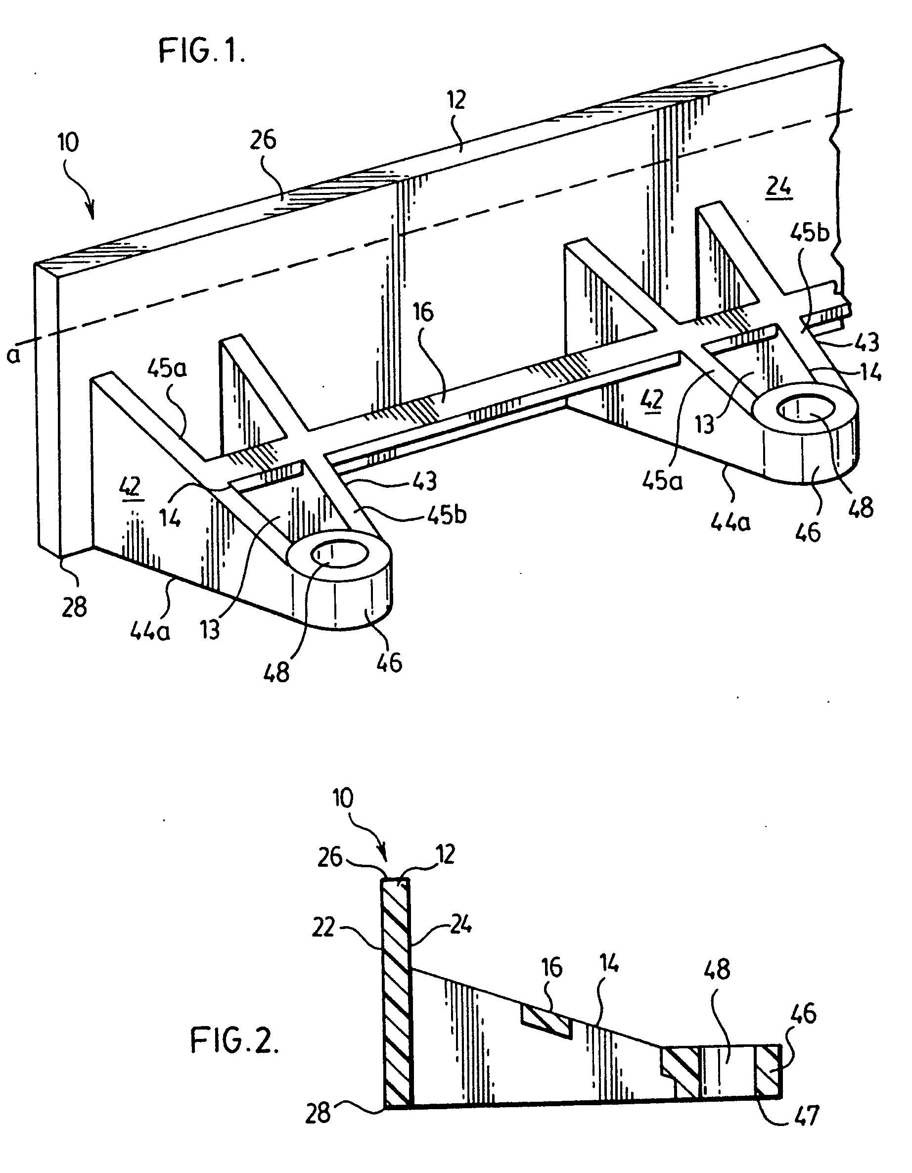
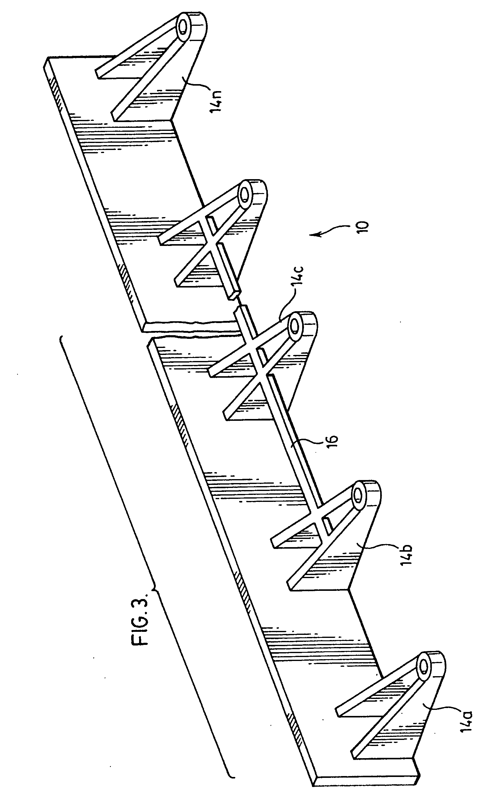
[0016]It will be appreciated by those skilled in the art that the embodiments of the apparatus referred to herein may be referred to as “restraints”, “edgings”, or “paver edgings”, without limitation of the described embodiments and the claimed invention herein. Further, it will be appreciated by those skilled in the art that while embodiments of the apparatus may be described herein with reference to installation and use for restraining or edging a paved surface paved with bricks or paving stones abutting or adjoining a region that is not paved, the embodiments herein include all possible paving means, such as bricks, paving stones, simulated rock facades, tile, wood planks, and other pavers of natural or artificial material, whether interlocking or otherwise regularly or randomly arranged. All such paving means are referred to herein as “paver”, and this terminology is not intended to be restrictive. The non-paved region described herein is a region that is not paved with paving m...


PUM


Abstract

A paver or landscape edging is provided with enhanced anchoring means. The edging has an elongated, longitudinal strip with a paver-facing surface and an opposed surface, and extensions extending from the opposed surface of the elongated strip, each comprising a first wall edge and a bore for receiving a fastener such as a spike or stake. A strap member extends between neighbouring extensions, offset from the first wall edge and defining a gap, or anchoring region, when the edging is placed on a substrate. The installed edging may be anchored by fasteners, and by root systems of a concealing layer placed over the edging that grow around the strap member. In addition, a method for installing pavers provides for the fixing of a portion of the edging on the substrate prior to cutting a strap to allow the edging to be deformed in conformance with a curved or irregular boundary.

Description

TECHNICAL BACKGROUND [0001]1. Technical Field[0002]This invention relates to paver and brick edgings, and the laying of brick and paving stones and the like.[0003]2. Description of the Related Art[0004]It is often desirable to cover a substrate, such as a terrestrial substrate like soil, sand, or gravel, with paving stones, bricks, and the like. The paving stones, bricks, or similar building materials thus provide a paved region. The paved surface may abut another region, such as a grassy lawn, a garden, or other soil, sand, or gravel-based region. When such a paving surface is installed, an edging or restraint may be simultaneously installed to maintain the paving stones within the region defined by the restraint. The edging reduces the likelihood that paving stones or bricks will shift horizontally as a result of traffic, or as a result of shifting of the underlying terrestrial substrate. These edgings may, once installed adjacent the paved region, protrude from the ground or may ...

Claims


Application Information

Patent Timeline
12 Feb 2009
Publication
US20090038238A1
IPC
A01G1/08; A01G9/28
CPC
A01G1/08; A01G9/28
Inventors
KURTZ, RUBIN; FRIEBERG, DAVID