
Stacked electrical connector with improved signal transmission

a technology of electrical connectors and stacked connectors, which is applied in the direction of coupling device connections, coupling protective earth/shielding arrangements, electric discharge lamps, etc., can solve the problems of not meeting the requirements of many electric devices, the transmission rate of usb is not sufficient, and the pci express and sata connectors cannot adapt to the development trend

Active Publication Date: 2009-02-12
HON HAI PRECISION IND CO LTD
View PDF4 Cites 57 Cited by
  • Summary
  • Abstract
  • Description
  • Claims
  • Application Information

AI Technical Summary

Problems solved by technology

However, as the development of electric industry, even the USB 2.0 can not satisfied the requirement of many electric devices.
For example, under a circumstance transmitting an audio or video file, which is always up to hundreds MB, even to 1 or 2 GB, currently transmission rate of USB is not sufficient.
However, these non-USB protocols, such as PCI Express which is useful for its higher possible data rates, a 26-pin connectors and wider card-like form factor limit the use of Express Cards, and SATA which uses two connectors, one 7-pin connector for signals and another 15-pin connector for power, are not used as broadly as USB protocols.
Due to its clumsiness, the PCI Express and SATA connector can not adapt to the development trend of gently, thin, short and small size.

Method used


Image

  • Stacked electrical connector with improved signal transmission
  • Stacked electrical connector with improved signal transmission
  • Stacked electrical connector with improved signal transmission

Examples


Embodiment Construction

[0042]In the following description, numerous specific details are set forth to provide a thorough understanding of the present invention. However, it will be obvious to those skilled in the art that the present invention may be practiced without such specific details. In other instances, well-known circuits have been shown in block diagram form in order not to obscure the present invention in unnecessary detail. For the most part, details concerning timing considerations and the like have been omitted inasmuch as such details are not necessary to obtain a complete understanding of the present invention and are within the skills of persons of ordinary skill in the relevant art.

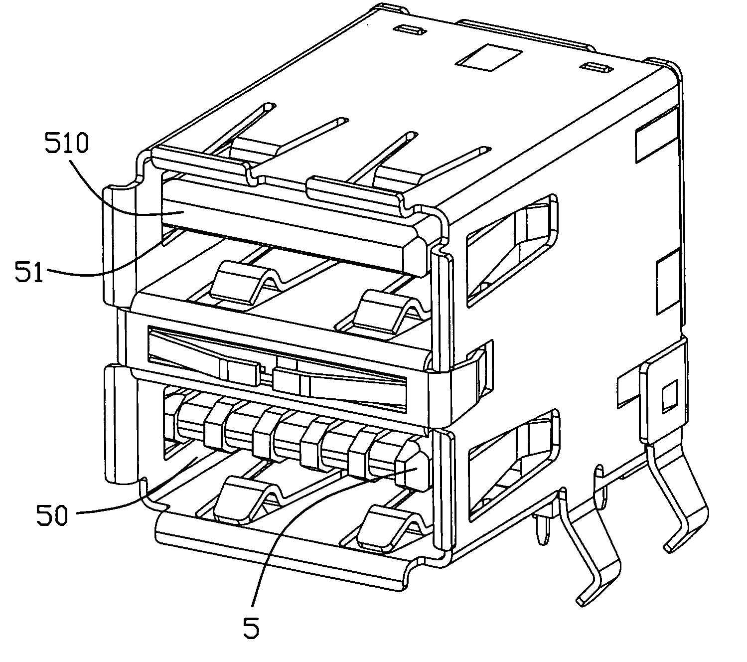
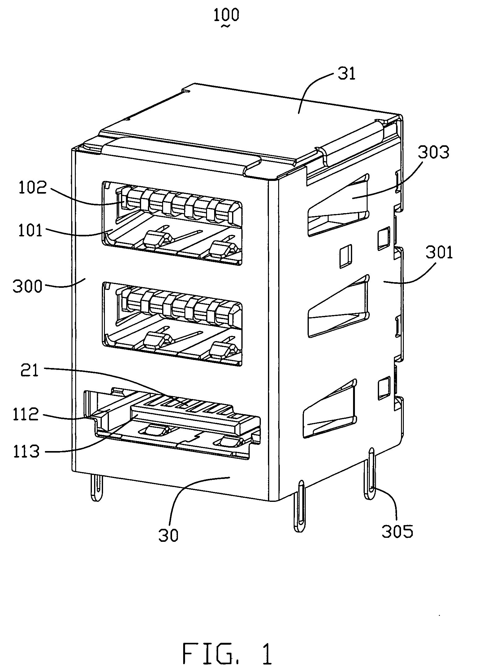
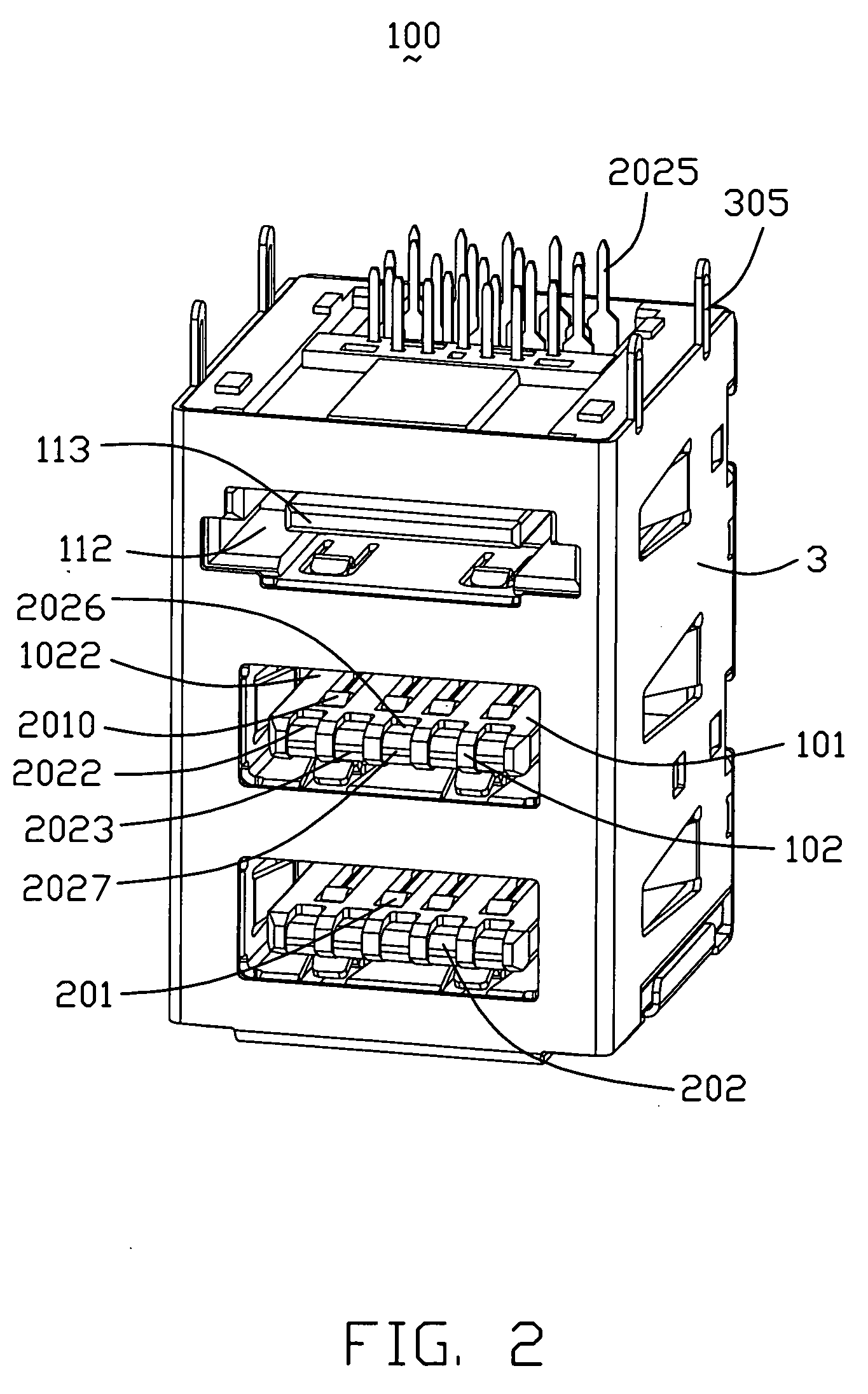
[0043]Referring to FIGS. 1-5, an stacked electrical connector 100 according to a first embodiment of the present invention is disclosed. The stacked electrical connector 100 comprises an insulative housing 1, a plurality of contacts 2 retained in the insulative housing 1, a metal shield 3 enclosing the insulati...


PUM


Abstract

A stacked electrical connector includes a first mating interface. The first mating interface comprises a first receiving space (101) with a first tongue (102). The first tongue (102) has a pair of upper and lower face (1021, 1022). A plurality of first contacts (20) are retained in the first mating interface. The first contacts (20) include a plurality of first elastic contacts (201) and a plurality of first flat contact (202). Each first elastic contact (201) has a securing portion (2011) fixed in the first mating interface (101), an elastic contact portion (2010) extending to the first tongue (102) and a soldering portion (2012). Each first flat contact (202) has a retention portion (2024, 2028) retained in the first mating interface (101), a flat contact portion (2022, 2026) extending to the first tongue (102) and a tail portion (2025, 2029). The flat contact portions (2022, 2026) and the elastic contact portions (2010) are located at a same side of the upper face (1021), and are arranged in two rows along a length direction of the first tongue (102). A second mating interface is stacked with the first mating interface along a thickness direction of the first tongue (102). A plurality of second contacts (21) are retained in the second mating interface.

Description

BACKGROUND OF THE INVENTION[0001]1. Field of the Invention[0002]The present invention relates to an stacked electrical connector, and more particularly to stacked electrical connectors with improved signal transmission.[0003]2. Description of Related Art[0004]Universal Serial Bus (USB) is used widely in variety electric devices as a standard and simple interface. As of 2006, the USB specification was at version 2.0 (with revisions). The USB 2.0 specification was released in April 2000 and was standardized by the USB-IF at the end of 2001. Previous notable releases of the specification were 0.9, 1.0, and 1.1. Equipment conforming to any version of the standard will also work with devices designed to any previous specification (known as: backward compatibility).[0005]USB mentioned above supports three data rates respectively as follows: 1) A Low Speed rate of up to 1.5 Mbit / s (187.5 KB / s) that is mostly used for Human Interface Devices (HID) such as keyboards, mice, and joysticks; 2) ...

Claims


Application Information

Patent Timeline
IPC IPC(8): H01R27/00
CPCH01R23/6873H01R12/712H01R24/62H01R2107/00H01R13/658H01R25/006H01R27/02
Inventor HE, JIA-YONGZHENG, QI-SHENGGU, HAOMAO, YU-LONGQIAO, FENG
Owner HON HAI PRECISION IND CO LTD
Features
  • Generate Ideas
  • Intellectual Property
  • Life Sciences
  • Materials
  • Tech Scout
  • Unparalleled Data Quality
  • Higher Quality Content
  • 60% Fewer Hallucinations
Learn More