Image processing apparatus and method

a technology of image processing and apparatus, applied in the field of image processing apparatus and method, can solve the problems of improving mechanical precision and inability to obtain satisfactory prints

Inactive Publication Date: 2009-03-12
SEIKO EPSON CORP
View PDF60 Cites 0 Cited by
  • Summary
  • Abstract
  • Description
  • Claims
  • Application Information

AI Technical Summary

Benefits of technology

Enables borderless printing on hybrid printers without margin regions, improving print quality while maintaining low product costs by adjusting scan and print settings to match the print medium's dimensions, thus addressing the discrepancy between scanner and printer margins.

Problems solved by technology

It has been the case with such hybrid printers, when printing is carried out as a result of instruction to cause printer mechanism to directly perform four-sided borderless printing of image captured from original by scanner mechanism onto printing paper identical in size to original, that, because scan region capable of being captured by scan mechanism is smaller than entire original surface region by amount corresponding to prescribed margins (hereinafter “scanner margins”), such scanner margins appear in unabated fashion on printing paper, making it impossible to obtain satisfactory print results.
Improvement of mechanical precision in connection with both scanning and printing in order to adjust such discrepancy between scan region of scanner mechanism and print region of printer mechanism has been a problem from the standpoint of product cost.

Method used


Image

  • Image processing apparatus and method
  • Image processing apparatus and method
  • Image processing apparatus and method

Examples


first embodiment

[0050]FIG. 1 is a drawing showing the external appearance of a hybrid printer associated with the present invention. This hybrid printer 1 has scanner functionality by which it captures document(s) or other such original(s) in the form of scan image data, and has printer functionality by which it converts scan image data, application data, and / or other such data subject to printing into print image data and carries out printing on printing paper. Provided at the interior of hybrid printer 1 there is / are control apparatus(es), control being carried out in comprehensive fashion by such control apparatus(es) and various functions being implemented thereby.

[0051]As shown in same drawing, provided at the top of the main body of hybrid printer 1 there are liquid crystal panel(s) and various buttons forming user interface(s) 11. User(s) can, by way of this user interface 11, scan original(s), give print instructions, enter various settings related to conditions in connection with scan, set...

second embodiment

[0074]Next, a hybrid printer in accordance with the present invention will be described.

[0075]Such a hybrid printer might, for example, have a constitution such as is shown in FIGS. 1 and 2, and might, moreover, be provided not only with hybrid printer functionality but also with functionality permitting it to also serve as standalone image scanner and functionality permitting it to also serve as standalone inkjet printer. Such a hybrid printer might have user-selectable scanner mode(s), printer mode(s), and hybrid printer mode(s), such modes being capable of being entered in alternative fashion in response to user request; i.e., such hybrid printer might be capable of being used in multimode fashion (such a hybrid printer will hereinafter be referred to as a “multimode hybrid printer”).

[0076]In the event that scanner mode has been specified, the multimode hybrid printer might carry out processing whereby image(s) of original(s) placed at prescribed location(s) on original stage(s) ...

third embodiment

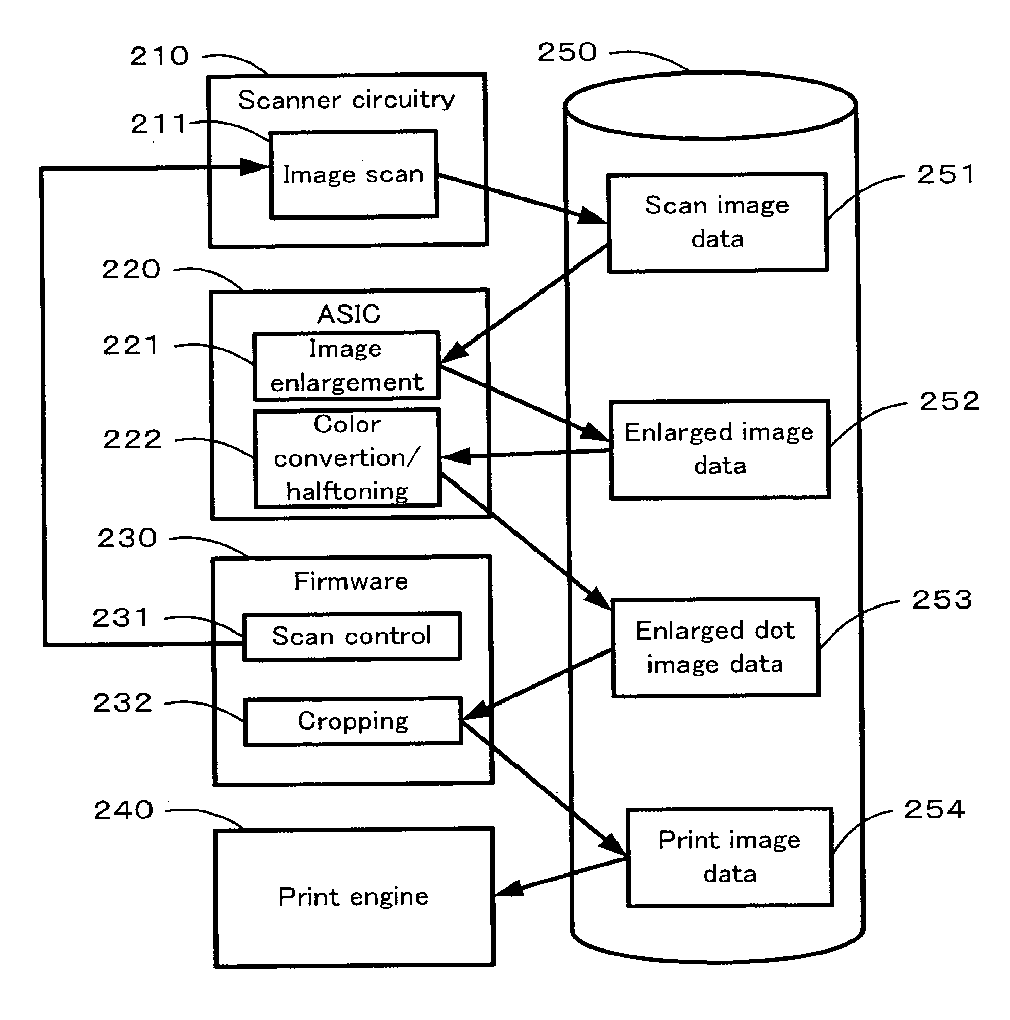
[0130]FIG. 16 shows constitution and function of the principal parts of a hybrid printer in accordance with the present invention.

[0131]This hybrid printer has mechanical construction as is shown in FIG. 1; furthermore, as shown in FIG. 16, there are at the interior thereof scanner circuitry 210, ASIC(s) (Application Specific IC(s)) 220, firmware (i.e., microprocessor(s) executing firmware) 230, print engine(s) 240, and storage device(s) 250.

[0132]Scanner circuitry 210 carries out image scan processing 211, scanning in image(s) of original(s) placed on original stage(s). At such time, firmware 230 carries out scan control 231, controlling image scan processing 211 so as to cause scanning of scan region(s) determined in correspondence to original size(s) specified by user(s). Original scan image data 251 output from scanner circuitry 210 is temporarily stored in storage device(s) 250 such as, for example, RAM and / or hard drive(s).

[0133]ASIC 220 reads scan image data 251 from storage ...


PUM


Abstract

An image scanner might capture an image corresponding to scan region 263 which might be somewhat larger than original 262. Image processing circuitry might then enlarge an image corresponding to scan region 263 (arrow 279), converting it into enlarged image 271. Within enlarged image 271, the image of original 262 might have been enlarged so as to become image 273, which might be somewhat larger than printing paper 274. This enlarged original image 273 which would be present within enlarged image 271 might then be printed by a printer. Four-sided borderless copying is possible.

Description

CROSS-REFERENCE TO RELATED APPLICATIONS[0001]This application is a divisional application of application Ser. No. 10 / 797,062 filed Mar. 11, 2004, which is a Continuation-In-Part Application of U.S. application Ser. No. 10 / 489,244 filed Mar. 11, 2004, which issued as U.S. Pat. No. 7,059,785, and which is a National Stage Application of PCT Application No. PCT / JP02 / 09328, filed Sep. 12, 2002. The entire disclosure of the aforementioned prior applications are hereby incorporated by reference in their entirety. This application claims benefit of foreign priorities to Japanese (JP) Patent Application No. 2001-276543, filed 12 Sep. 2001, Japanese (JP) Patent Application No. 2001-399255, filed 28 Dec. 2001, Japanese (JP) Patent Application No. 2003-066271, filed 12 Mar. 2003, and Japanese (JP) Patent Application No. 2004-038890, filed 16 Feb. 2004, the contents of which are incorporated herein by reference in their entirety.FIELD OF ART[0002]The present invention pertains to an image proce...

Claims


Application Information

Patent Timeline
Patent Type & AuthorityApplications(United States)
IPC IPC(8): H04N1/04H04N1/387
CPCH04N1/3875
InventorYADA, JUNYAKATO, TAKASHI
OwnerSEIKO EPSON CORP