Ribbon microphone and ribbon microphone unit

a microphone and ribbon technology, applied in the direction of deaf-aid sets, electrical transducers, electrical apparatus, etc., can solve the problems of affecting the performance the easy movement of the ribbon diaphragm, and achieve the effect of convenient and convenient carrying ou

Active Publication Date: 2009-05-07
AUDIO-TECHNICA
View PDF9 Cites 10 Cited by
  • Summary
  • Abstract
  • Description
  • Claims
  • Application Information

AI Technical Summary

Benefits of technology

[0020]The ribbon microphone unit according to the present invention comprises the magnetic-circuit assembly and the ribbon diaphragm assembly (hereinafter, referred to as the “diaphragm assembly”), and each of them is detachable. This structure allows a user side to detach the diaphragm assembly from the magnetic-circuit assembly and carry out the maintenance, such as the tension adjustment, replacement, and the like of the ribbon diaphragm. In particular, the replacement of the diaphragm assembly can be easily carried out by detaching the diaphragm assembly from the magnetic-circuit constituting portion and then by attaching a new diaphragm assembly, and therefore the magnetic-circuit assembly needs not be replaced. Moreover, the replacement of the magnetic-circuit assembly can be easily carried ou

Problems solved by technology

However, if the resonance frequency of the ribbon diaphragm is too low, such a problem will occur that the ribbon diaphragm easily moves to contact a pole for forming the magnetic field when a wind blows against the ribbon diaphragm or when a vibration is applied thereto.
However, since the aluminum foil

Method used


Image

  • Ribbon microphone and ribbon microphone unit
  • Ribbon microphone and ribbon microphone unit
  • Ribbon microphone and ribbon microphone unit

Examples


Embodiment Construction

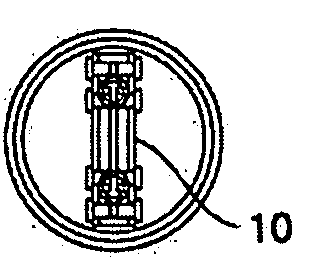
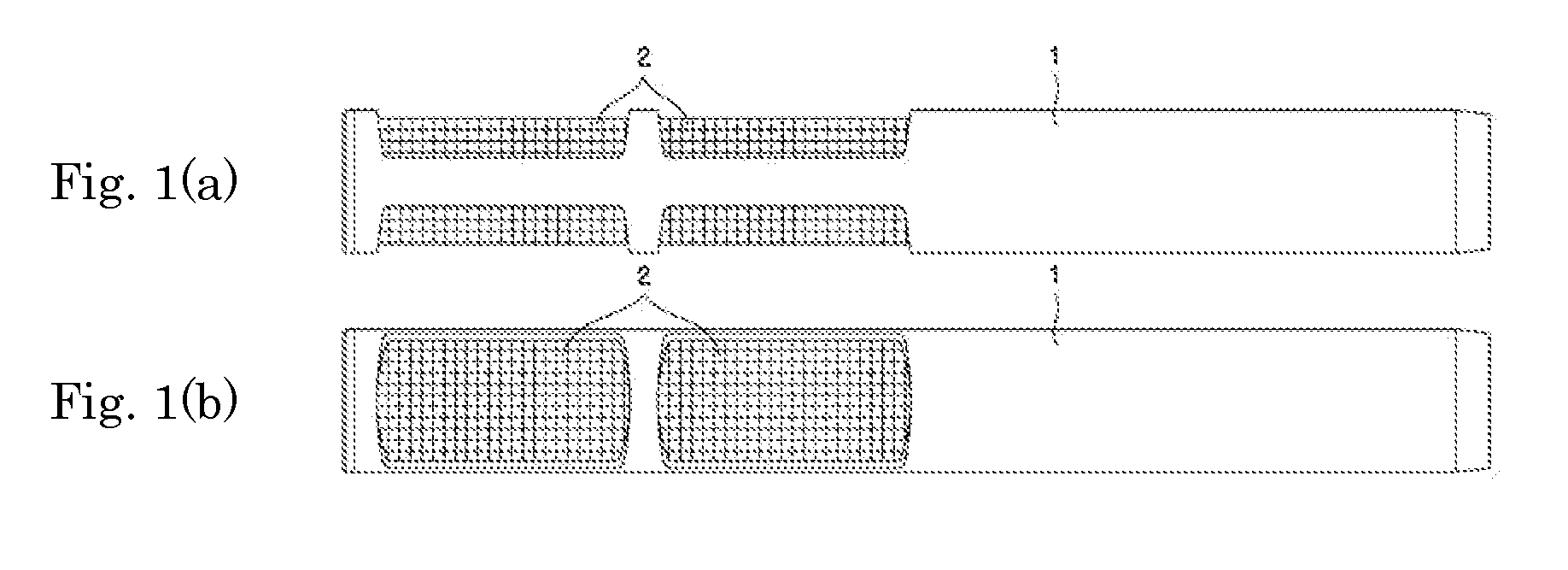
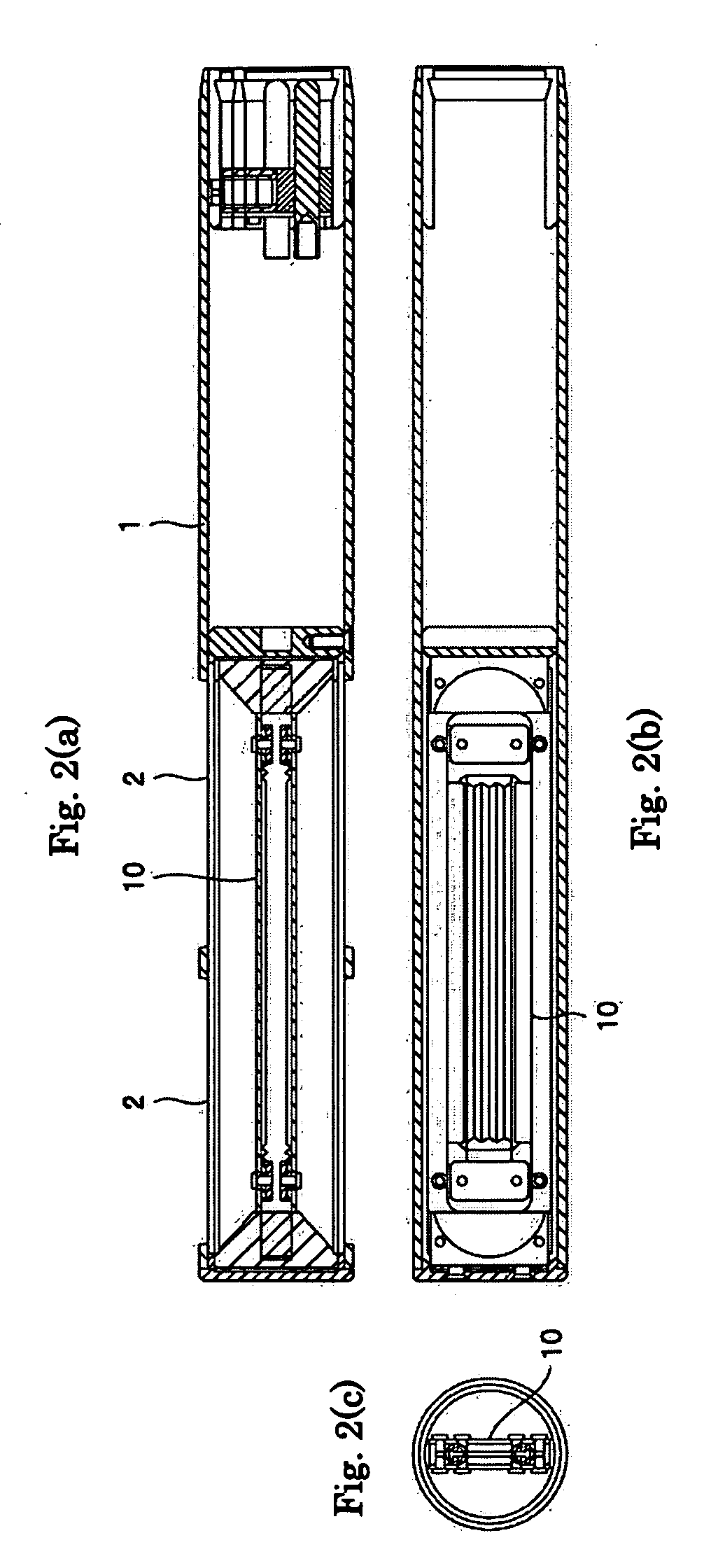
[0038]Hereinafter, the embodiments of a ribbon microphone and a ribbon microphone unit according to the present invention will be described with reference to the accompanying drawings. In FIG. 1, reference numeral 1 denotes a microphone case. The microphone case 1 is cylindrical, and in the wall surface thereof, on the positions having a mutually front-rear relation, from the center portion to the tip portion, two rectangular window holes that are long in the longitudinal direction are formed side by side in the longitudinal direction of the microphone case 1, respectively. A mesh 2 is stuck to these window holes. Sounds from the outside of the microphone case 1 pass through the mesh 2, and reach a microphone unit disposed inside the microphone case 1. In FIG. 2, reference numeral 10 denotes the microphone unit. The microphone unit 10 is installed in the center position inside the microphone case 1 and corresponding to the attached position of the mesh 2.

[0039]As shown in FIGS. 3(a)...


PUM


Abstract

To obtain a ribbon microphone unit, which makes the tension of a diaphragm adjustable by configuring a ribbon diaphragm assembly that is detachable to a magnetic-circuit assembly including a magnet, and which further allows a user side to carry out the maintenance by replacing the ribbon diaphragm assembly; a ribbon microphone unit comprises: a magnetic-circuit assembly including a magnet; and a ribbon diaphragm, wherein the ribbon diaphragm, together with a substrate having a circuit pattern formed on both ends thereof, a metal fitting for crimping an end portion of the ribbon diaphragm to the circuit pattern, and a screw for crimping the metal fitting toward the substrate, constitute a diaphragm assembly, and wherein the diaphragm assembly is secured to the magnetic-circuit assembly.

Description

BACKGROUND OF THE INVENTION[0001]1. Field of the Invention[0002]The present invention relates to ribbon microphones and ribbon microphone units.[0003]2. Related Background of the Invention[0004]A ribbon microphone includes a magnet for forming a magnetic field and a ribbon diaphragm, as main component members. The magnet is disposed on both sides of the ribbon diaphragm to sandwich the same, whereby a magnetic field is formed between the magnets on the both sides. The ribbon diaphragm is given an appropriate tension and disposed within the magnetic field while the both longitudinal ends are held down. In response to a sound wave, the ribbon diaphragm vibrates within the magnetic field and thereby a current corresponding to the sound wave flows through the ribbon diaphragm and thus the sound wave is converted into an electric signal. Generally, an aluminum foil is used as the material of the ribbon diaphragm. Since aluminium has an excellent electrical conductivity as compared with o...

Claims


Application Information

Patent Timeline
IPC IPC(8): H04R11/04
CPCH04R9/048H04R9/08H04R2307/027H04R31/006
Inventor AKINO, HIROSHI
Owner AUDIO-TECHNICA
Why Eureka
Try Eureka