Portable electronic device

Active Publication Date: 2009-10-29
UNIVERSAL SCIENTIFIC INDUSTRIAL (SHANGHAI) CO LTD +1
View PDF5 Cites 28 Cited by
  • Summary
  • Abstract
  • Description
  • Claims
  • Application Information

AI Technical Summary

Benefits of technology

[0006]Therefore, the object of the present invention is to provide a portable elec

Problems solved by technology

Therefore, the conventional electronic device 10 ca

Method used


Image

  • Portable electronic device
  • Portable electronic device
  • Portable electronic device

Examples


Example

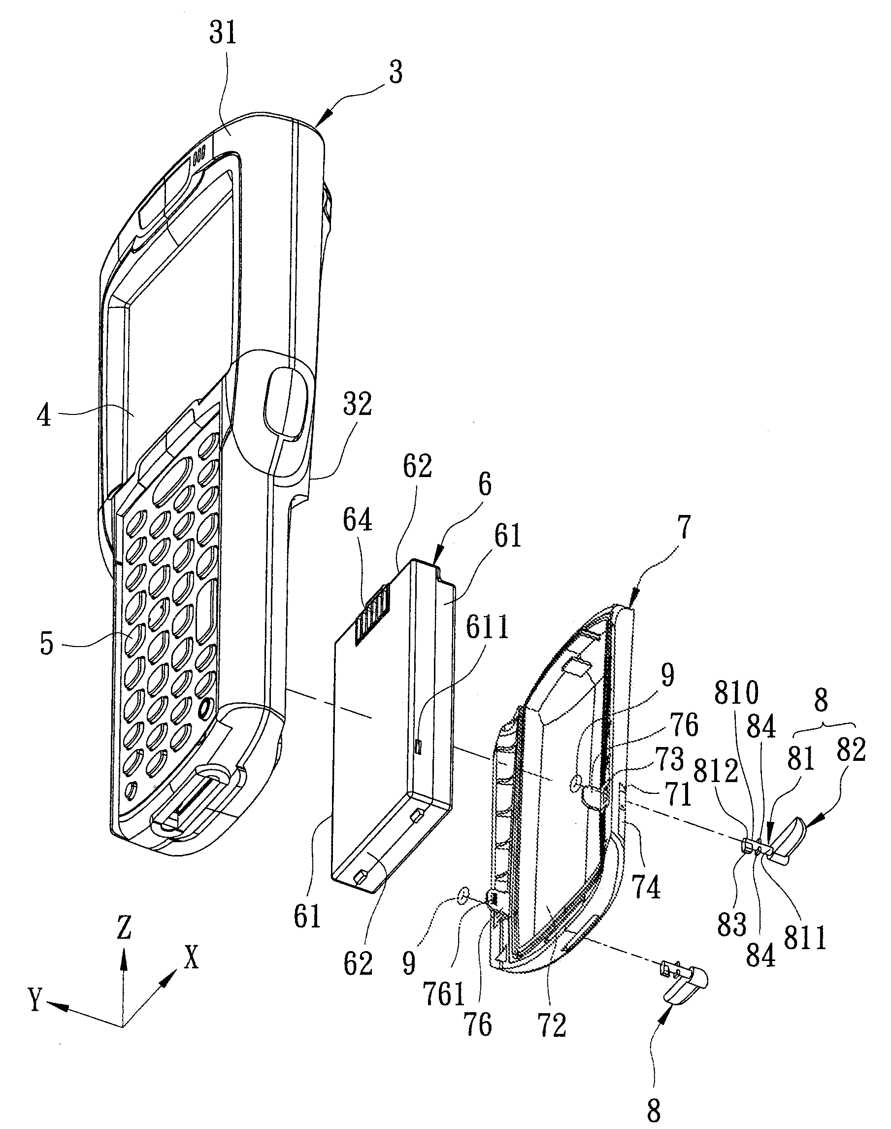
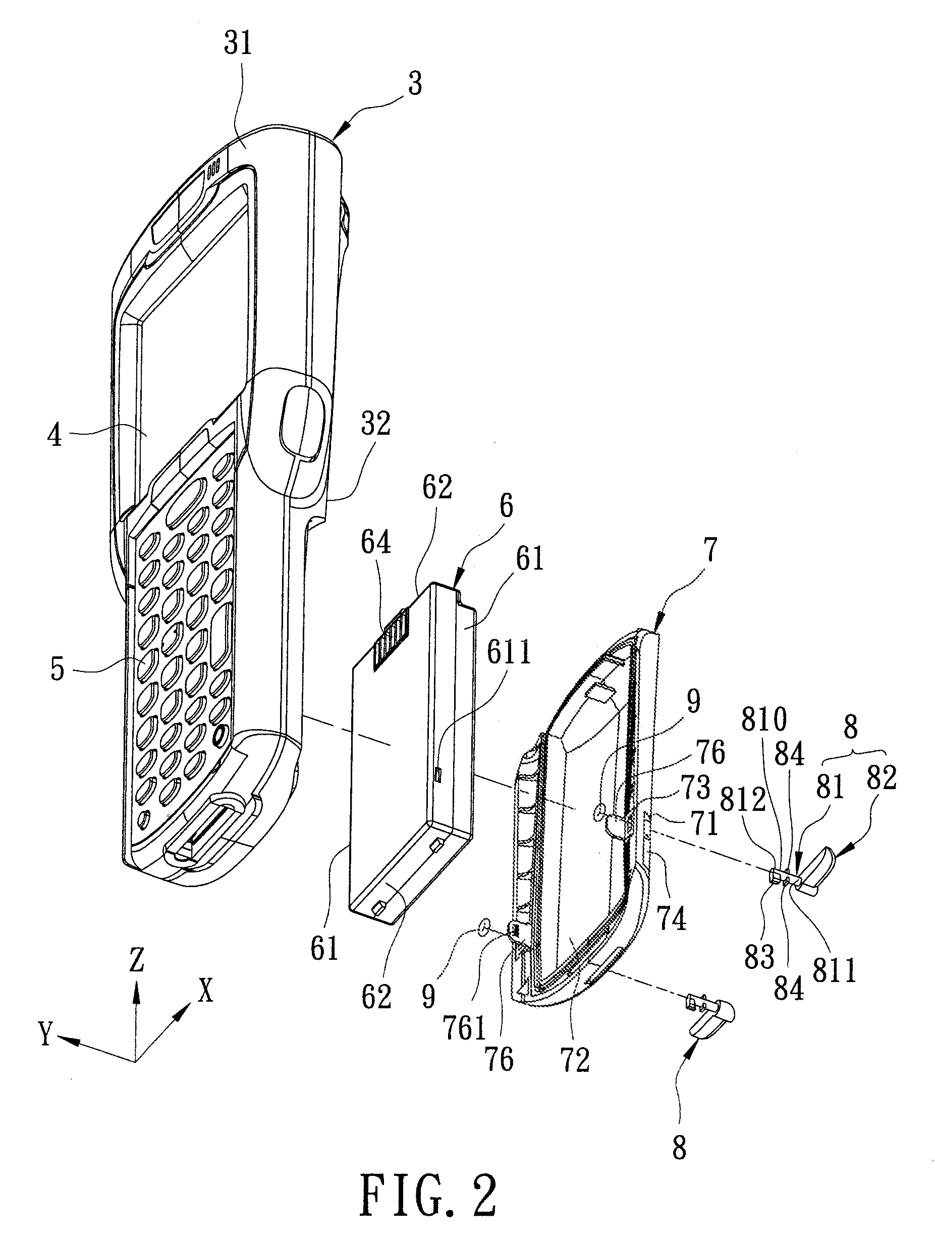
[0020]Referring to FIGS. 2 and 3, the preferred embodiment of a portable electronic device according to the present invention is shown to include a battery 6, a main casing 3, a cover 7, and two anchoring members. In this embodiment, the portable electronic device is an industrial personal digital assistant (PDA).

[0021]The battery 6 has two first side surfaces 61 opposite to each other in a first direction (Y), and two second side surfaces 62 opposite to each other in a second direction (Z) perpendicular to the first direction (Y).

[0022]The main casing 3 has first and second side surfaces 31, 32 opposite to each other in a third direction (X) perpendicular to the first and second directions (Y, Z). In this embodiment, the first and second side surfaces 31, 32 can be respectively regarded as front and rear side surfaces. A display 4 and a keypad 5 are mounted on the first side surface 31 of the main casing 3, as shown in FIG. 2. The second side surface 32 of the main casing 3 is form...


PUM


Abstract

A portable electronic device includes a main casing having a battery-receiving groove for receiving a battery therein, and two aligned resilient abutting tongues flanking the battery-receiving groove. A cover is mounted removably on the main casing for covering the battery-receiving groove. Two anchoring members are mounted rotatably on the cover, extends into the main casing, and is operable so as to switch between a releasing state, where the abutting tongues are spaced respectively apart from the battery, and a clamping state, where the abutting tongues are pressed respectively against the battery.

Description

BACKGROUND OF THE INVENTION[0001]1. Field of the Invention[0002]The invention relates to portable electronic device, more particularly to a portable electronic device having a housing device for receiving a battery.[0003]2. Description of the Related Art[0004]FIG. 1 illustrates a conventional portable electronic device 10, such as a mobile phone, that includes a main housing 11 formed with a battery-receiving groove 111 for receiving a battery 12 therein, and a cover 13 mounted detachably on the main housing 11 for covering the battery-receiving groove 111.[0005]In such a configuration, although the cover 13 is anchored to the main housing 11 by engagement between two positioning blocks 131 of the cover 13 and two positioning holes 112 in the main housing 11, the battery 12 cannot be positioned effectively in the battery-receiving groove 111. As a result, electrical disconnection between the battery 12 and an electrical contact (not shown) may occur when the conventional portable el...

Claims


Application Information

Patent Timeline
IPC IPC(8): H04B1/38H05K7/00H04M1/00
CPCH01M2/1066H04M1/0262H04B1/3883Y02E60/10
Inventor SU, FEI-MINGTSENG, JIA-HAO
Owner UNIVERSAL SCIENTIFIC INDUSTRIAL (SHANGHAI) CO LTD
Why Eureka
Try Eureka