Electrical connector having pull tether for latch release

a technology of electrical connectors and latches, which is applied in the direction of electrical apparatus, connection, coupling device connection, etc., can solve the problems of affecting the latching mechanism, affecting the latching, and affecting the latching ability of the technician, etc., and achieves the effect of adequate resiliency

Active Publication Date: 2009-11-05
TYCO ELECTRONICS LOGISTICS AG (CH)
View PDF31 Cites 27 Cited by
  • Summary
  • Abstract
  • Description
  • Claims
  • Application Information

AI Technical Summary

Benefits of technology

[0006]Optionally, the latch may include a distal end and a fixed end, wherein the latch includes a window proximate the distal end. The tether may be received in the window. The latch may include a latching surface configured to engage a corresponding latching surface of a mating connector, wherein the latching surface is moved relatively closer to the housing when the latch is depressed to the unlatched position. Optionally, the tether may include an embossment extending therefrom, wherein the embossment engages the latch as the tether is moved to the actuated position. The embossment may have a ramp surface extending from a base to a tip. The latch may ride along the ramp surface toward the tip as the tether moves to the actuated position. The latch may ride along the ramp surface toward the base as the tether moves to the released position. Optionally, the latch may have adequate resiliency to return to the latched position when the tether is released.

Problems solved by technology

Because the rows are positioned in such close proximity, difficulties arise for a technician to access the latching mechanism that is used to secure the connector to the panel.
The spacing between the connectors is simply too small to accommodate the technician's fingers to release the latching mechanism.
The cables and / or the connectors tend to block access to the latching mechanism, particularly when the connectors are arranged in multiple rows.
Damage may be caused to the latching mechanism or the connector itself by the technician when trying to reach the latching mechanism.
However, such tools are cumbersome to use.

Method used


Image

  • Electrical connector having pull tether for latch release
  • Electrical connector having pull tether for latch release
  • Electrical connector having pull tether for latch release

Examples


Embodiment Construction

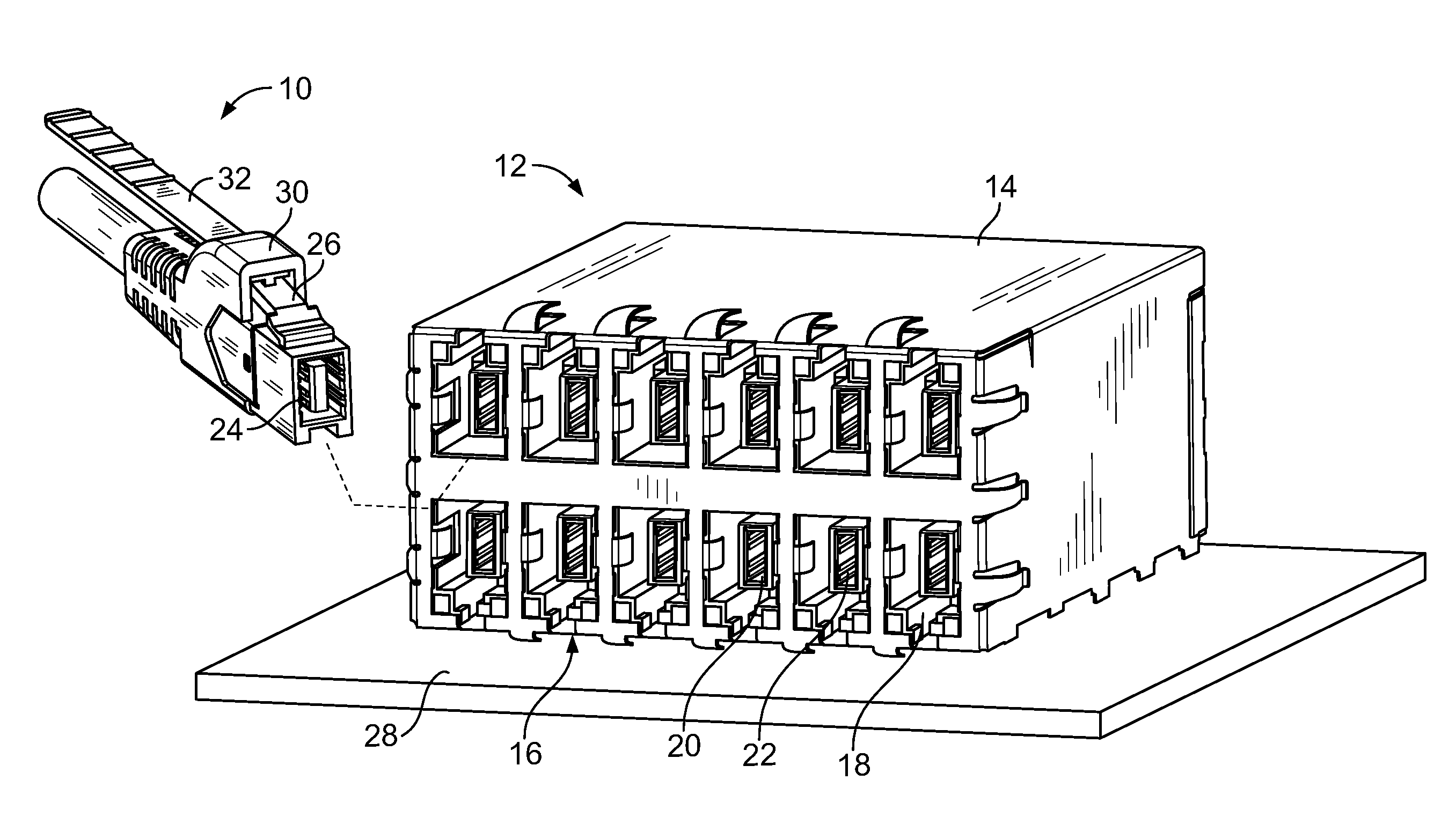
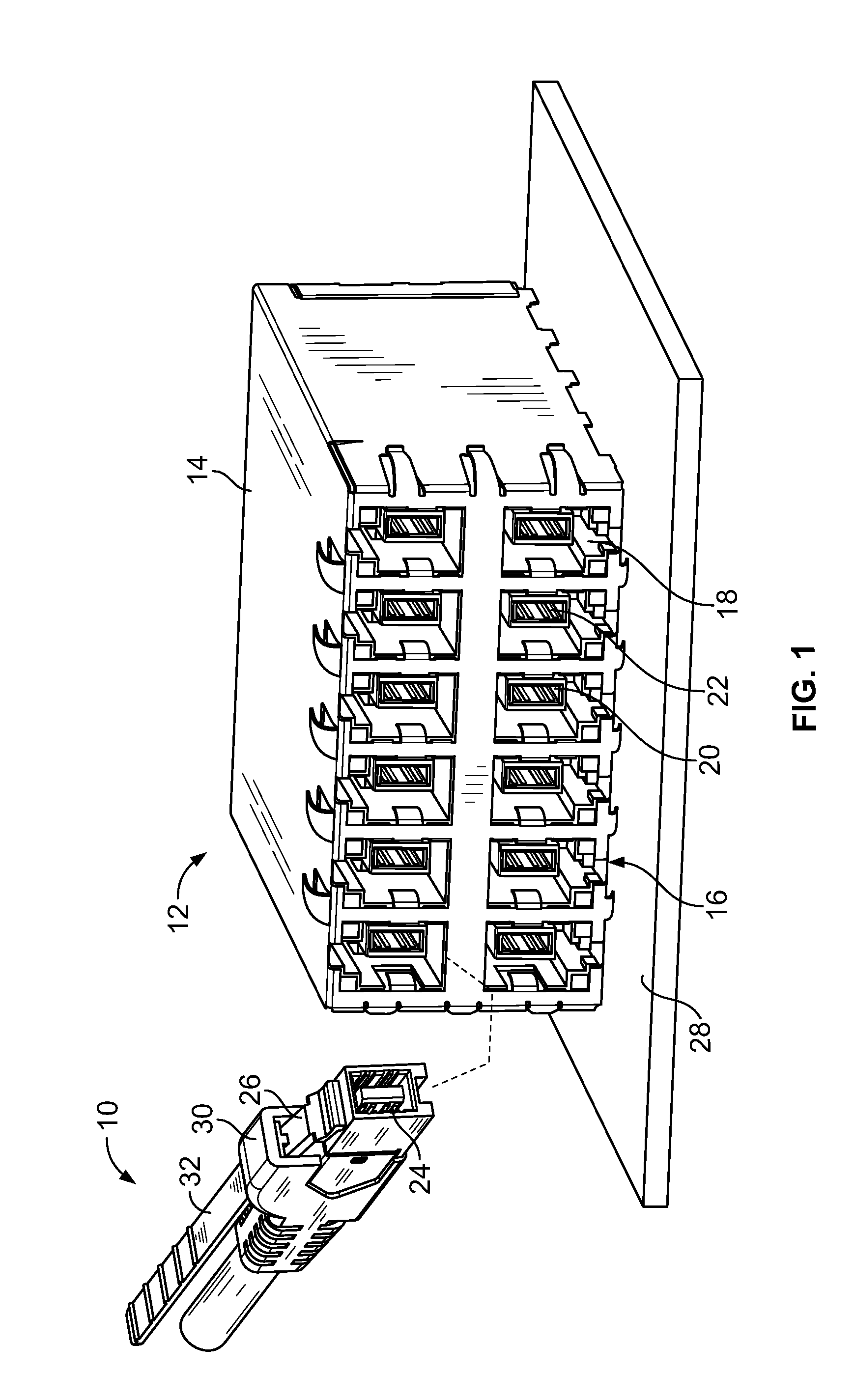
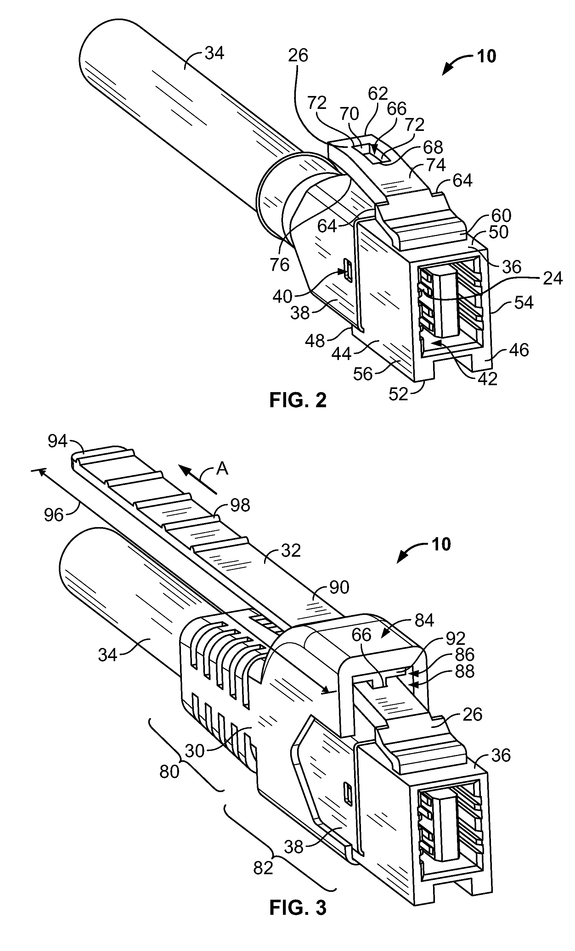
[0014]FIG. 1 is a perspective view of an exemplary electrical connector 10 formed in accordance with an exemplary embodiment. The electrical connector 10 represents a plug connector that may be mated with a mating connector 12, represented by the receptacle connector in FIG. 1. The electrical connector 10 and the mating connector 12 are modular connectors, such as the types of electrical connectors used for connecting telecommunications equipment or computer networking equipment. In the illustrated embodiment, the electrical connector 10 and the mating connector 12 are eight pin, eight conductor (8P8C) modular connectors having signal pairs, however the subject matter described herein also has applicability to other connectors having fewer or greater numbers of pins, conductors and / or signal pairs.

[0015]In an exemplary embodiment, the mating connector 12 includes a housing 14 having multiple communication ports 16 opening to receptacles 18 that receive respective ones of the electri...


PUM


Abstract

An electrical connector includes a housing having a plurality of contacts defining a mating interface for a mating connector. A latch extends from the housing and is configured to securely couple the housing to the mating connector. The latch is depressible to an unlatched position. A tether is mated with the latch. The tether is movable between a released position and an actuated position, wherein the tether depresses the latch to the unlatched position when the tether is moved to the actuated position.

Description

BACKGROUND OF THE INVENTION[0001]The subject matter herein relates generally to electrical connectors, and more particularly, to pull tethers for releasing latches of electrical connectors.[0002]In the electronics industry, and in particular the telecommunications industry, there is an increasing trend towards smaller electrical connectors, particularly cable mounted plugs. The industries are also trending to more densely packaged connectors and connector systems. For example, in switching networks, such as patch panels, the connectors are positioned in multiple rows in tightly spaced areas. Other examples include computers having multiple ports arranged on a panel. The ports are typically arranged in a plurality of rows that are spaced close to one another.[0003]Because the rows are positioned in such close proximity, difficulties arise for a technician to access the latching mechanism that is used to secure the connector to the panel. The spacing between the connectors is simply t...

Claims


Application Information

Patent Timeline
Patent Type & Authority Applications(United States)
IPC IPC(8): H01R13/627
CPCH01R13/6335H01R13/6272
Inventor HENRY, RANDALL R.PHILLIPS, MICHAEL J.RIX, ROBERT D.
Owner TYCO ELECTRONICS LOGISTICS AG (CH)
Why Eureka
Try Eureka