Low profile electrical connector

a low-profile, electrical connector technology, applied in the direction of fixed connections, computer periphery connectors, coupling contact members, etc., can solve the problems that all aforementioned designs are not suitable for the low-profile socket of the connector, and achieve the effect of reliable retention and sufficient resiliency

Active Publication Date: 2020-05-12
FOXCONN INTERCONNECT TECH LTD
View PDF21 Cites 4 Cited by
  • Summary
  • Abstract
  • Description
  • Claims
  • Application Information

AI Technical Summary

Benefits of technology

[0006]An object of the present invention is to provide an electrical connector of a low profile configuration with the corresponding contacts having reliable retention and sufficient resiliency thereof.

Problems solved by technology

Anyhow, all aforementioned designs are not fit for the low profile socket of the connector.

Method used


Image

  • Low profile electrical connector
  • Low profile electrical connector
  • Low profile electrical connector

Examples


Embodiment Construction

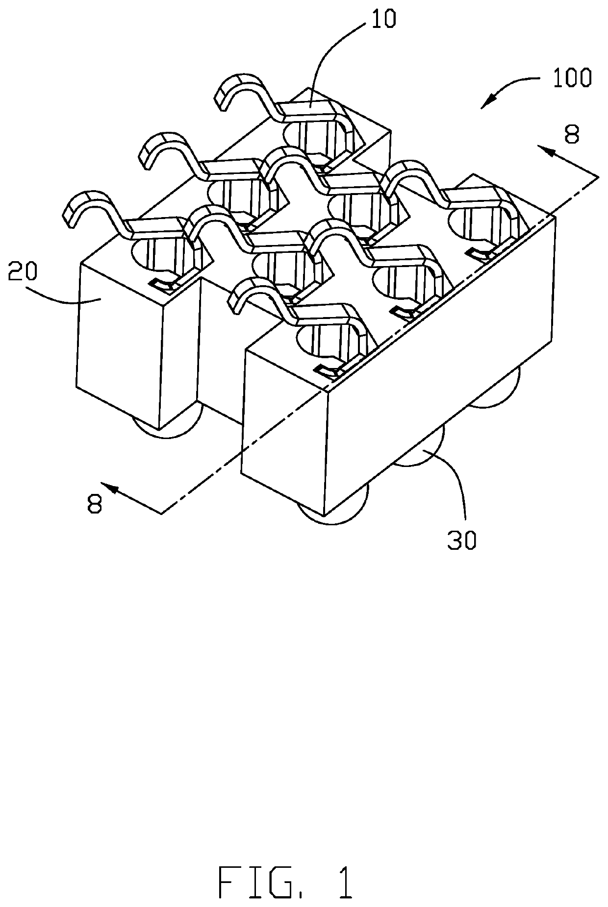
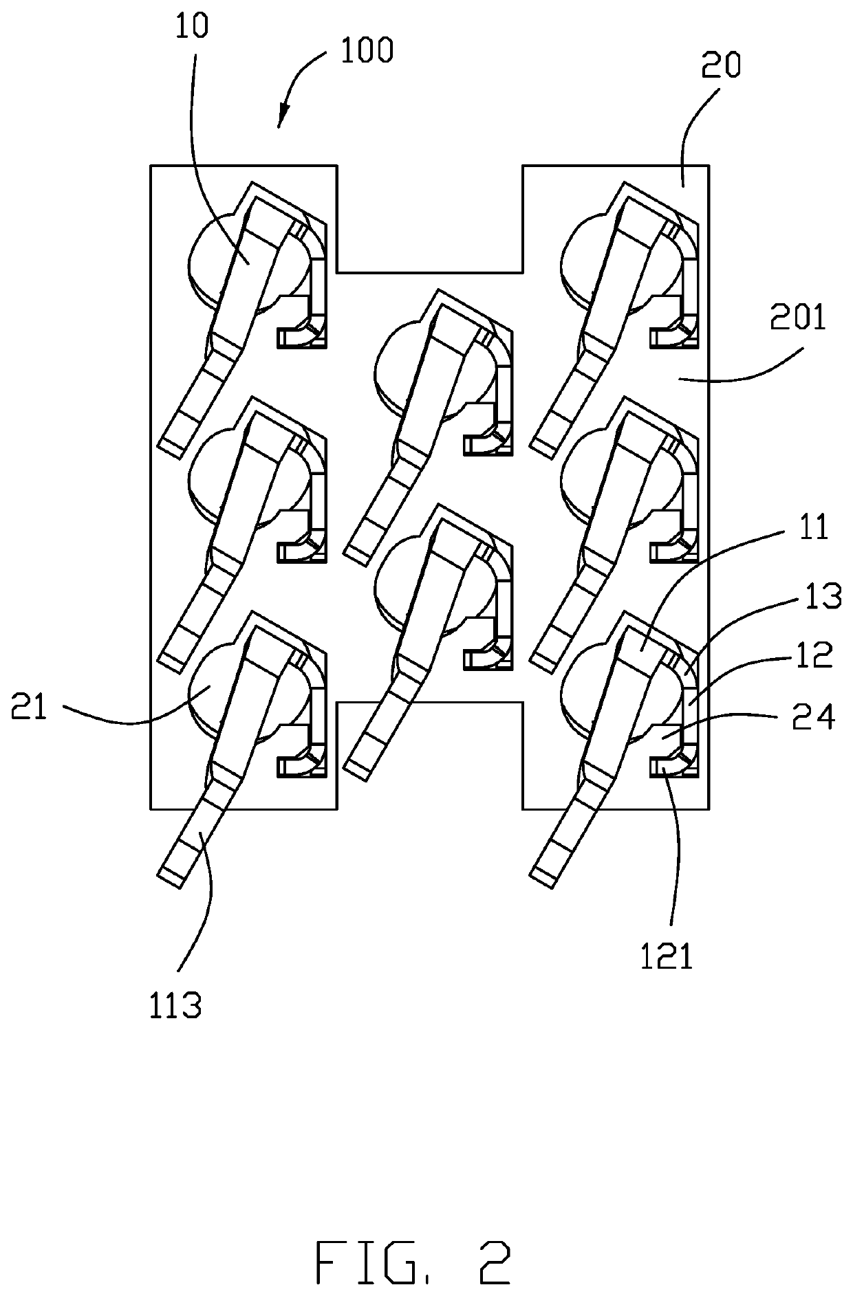
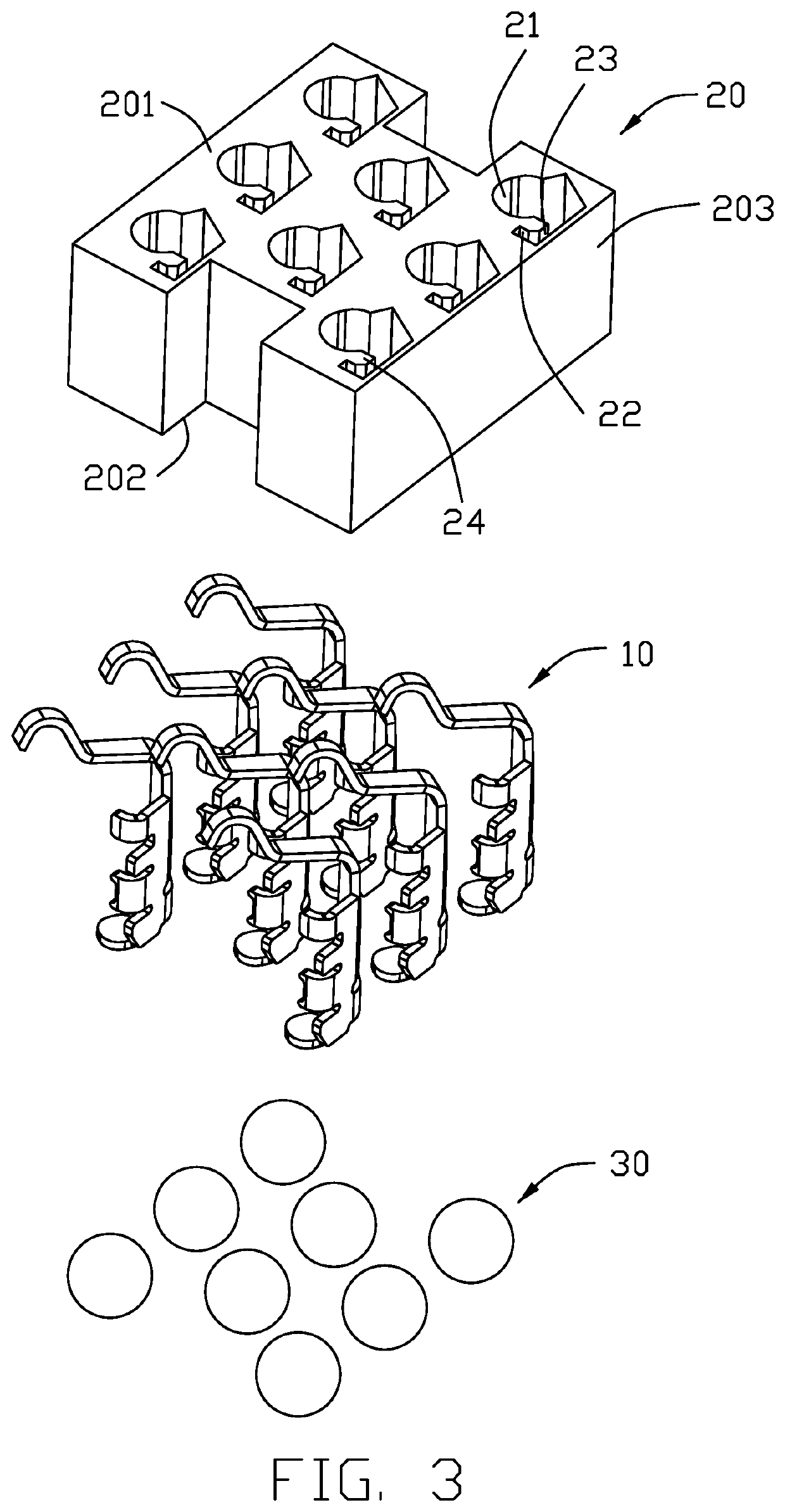
[0017]Reference will now be made to the drawing figures to describe a preferred embodiment of the present invention in detail. Referring to FIG. 1 to FIG. 8, an electrical connector 100 for connecting the CPU (Central Processing Unit) (not shown) to the printed circuit board (not shown), includes an insulative housing 20, a plurality of contacts 10 and a plurality of solder balls 30 attached to the corresponding contacts 10, respectively.

[0018]The contact 10 includes a first body 11, a second body 12 and a connection section 13 linked therebetween. A first retention section 121 and a second retention section 122, and a first abutting tab 123 and a second abutting tab 124 are alternately formed on an outer lateral side of the second body 12 opposite to the first body 11. The housing 20 forms a plurality of receiving cavities 21 each of which receives the first body 11 and the second body 12 of the corresponding contact 10, and a plurality of retention slots 22 each of which receives ...


PUM


Abstract

An electrical connector includes an insulative housing, a plurality of conductive contacts retained in the insulative housing, each contact has a first body, a resilient arm extending upwardly and obliquely from an upper side of the first body, a soldering section extending downwardly from a lower side of the first body, and a second body extending from a lateral side of the first body in an oblique direction and having a retention section formed on an outer lateral side thereof opposite to the first body. The housing forms a receiving cavity for receiving both the first body and the second body, and a retention slot for receiving the retention section.

Description

BACKGROUND OF THE INVENTION[0001]1. Field of the Invention[0002]The present invention relates to an electrical connector, and more particularly to an electrical connector having a low profile thereof with efficiently resilient contacting arms thereof.[0003]2. Description of the Prior Art[0004]U.S. Pat. Nos. 6,652,329 and 7,563,107 disclose the contact of the electrical connector having the contacting section and the retention section with the associated soldering section located in different planes oblique to each other. Chinese Patent No. CN201303090Y also discloses the contact of the electrical connector having the retention section and the contacting section with the associated soldering section located at different planes oblique to each other. Anyhow, all aforementioned designs are not fit for the low profile socket of the connector.[0005]Therefore, an improved electrical connector is highly desired to meet the low profile requirement.SUMMARY OF THE INVENTION[0006]An object of ...

Claims


Application Information

Patent Timeline
Patent Type & Authority Patents(United States)
IPC IPC(8): H01R13/24H01R13/40H01R12/58H01R12/71H01R13/428H01R12/70
CPCH01R13/428H01R12/58H01R12/707H01R13/245H01R13/40H01R13/2442H01R12/712H01R2201/06H01R12/57
Inventor HSU, SHUO-HSIU
Owner FOXCONN INTERCONNECT TECH LTD
Why Eureka
Try Eureka