Quick-action locking device for an electric power tool

a technology of electric power tools and locking devices, which is applied in the direction of mechanical control devices, instruments, gearing, etc., can solve the problems of increasing the dimensions prolonging the service life of the locking device, etc., and achieves the effects of high clamping force, economic manufacturing, and the ability to withstand large loads

Inactive Publication Date: 2005-10-11
HILTI AG
View PDF10 Cites 16 Cited by
  • Summary
  • Abstract
  • Description
  • Claims
  • Application Information

AI Technical Summary

Benefits of technology

[0016]Advantageously, the slider is formed as an annular support member having a predetermined radius and an axis of which extends parallel to the pivot axis. Such a slider insures an economical manufacturing, while permitting to obtain high clamping forces. Annular support elements (bearings) are generally characterized by their ability to withstand large loads, small friction, and a long service life. Their manufacture is very cost-effective as there is a need in a large number of them.
[0017]According to advantageous embodiment of the invention, the radius of the annular support element or member amounts to from 0.2 to 0.6 of the radial distance between the contact region of the slider and the pivot axis and, preferably, to 0.4 of the radial distance. A slider with such a radius permits to obtain optimal setting characteristics.

Problems solved by technology

Moreover, contrary to conventional quick-action locking devices, the use of sliders permits to substantially reduce wear, which substantially prolongs the service life of the locking device even with an excessive loading of the power tool.
However, a large travel path of the locking spindle increases the dimensions of the locking device as the size of the contact surface increases with the increase of the pivot angle.

Method used


Image

  • Quick-action locking device for an electric power tool
  • Quick-action locking device for an electric power tool
  • Quick-action locking device for an electric power tool

Examples


Embodiment Construction

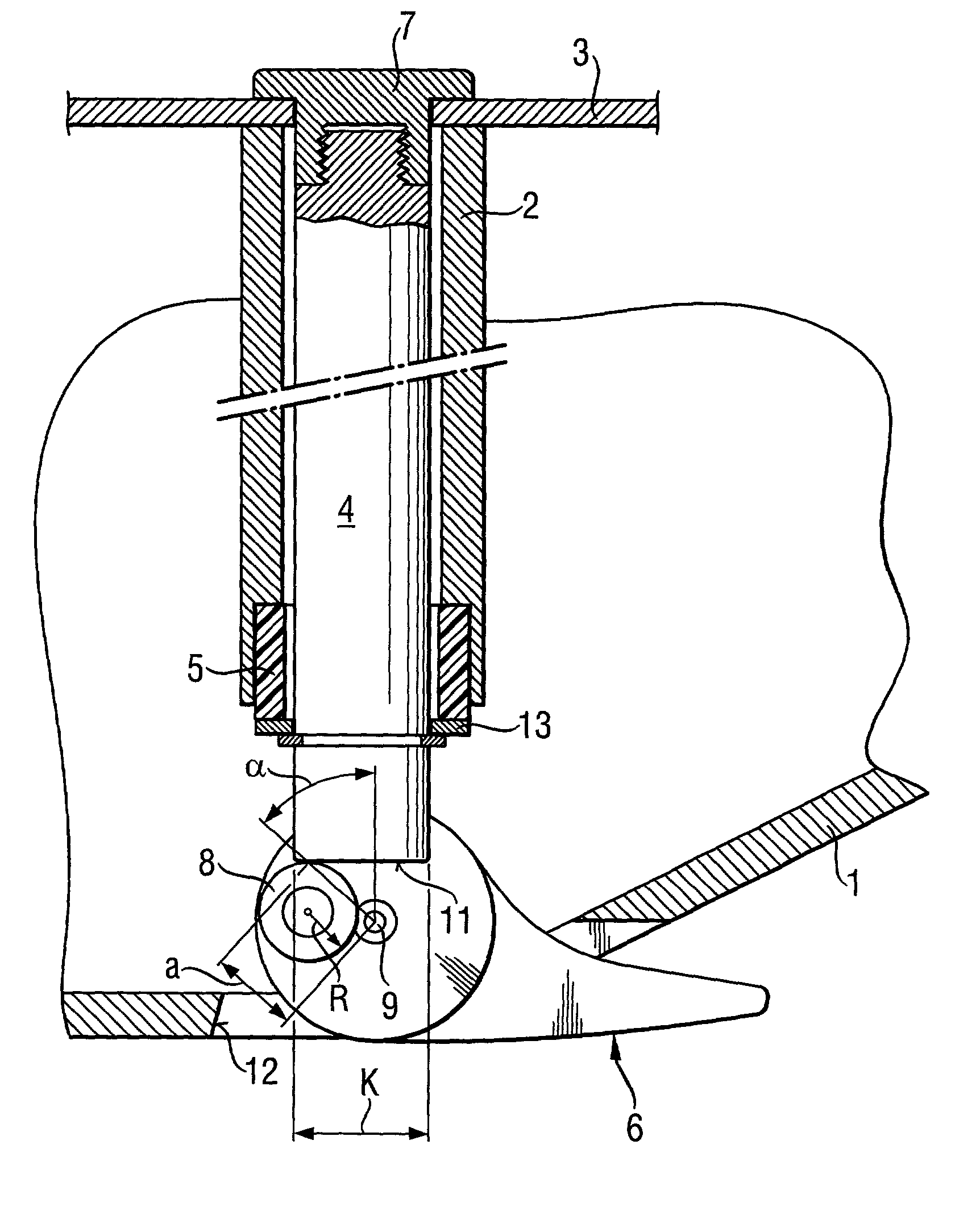
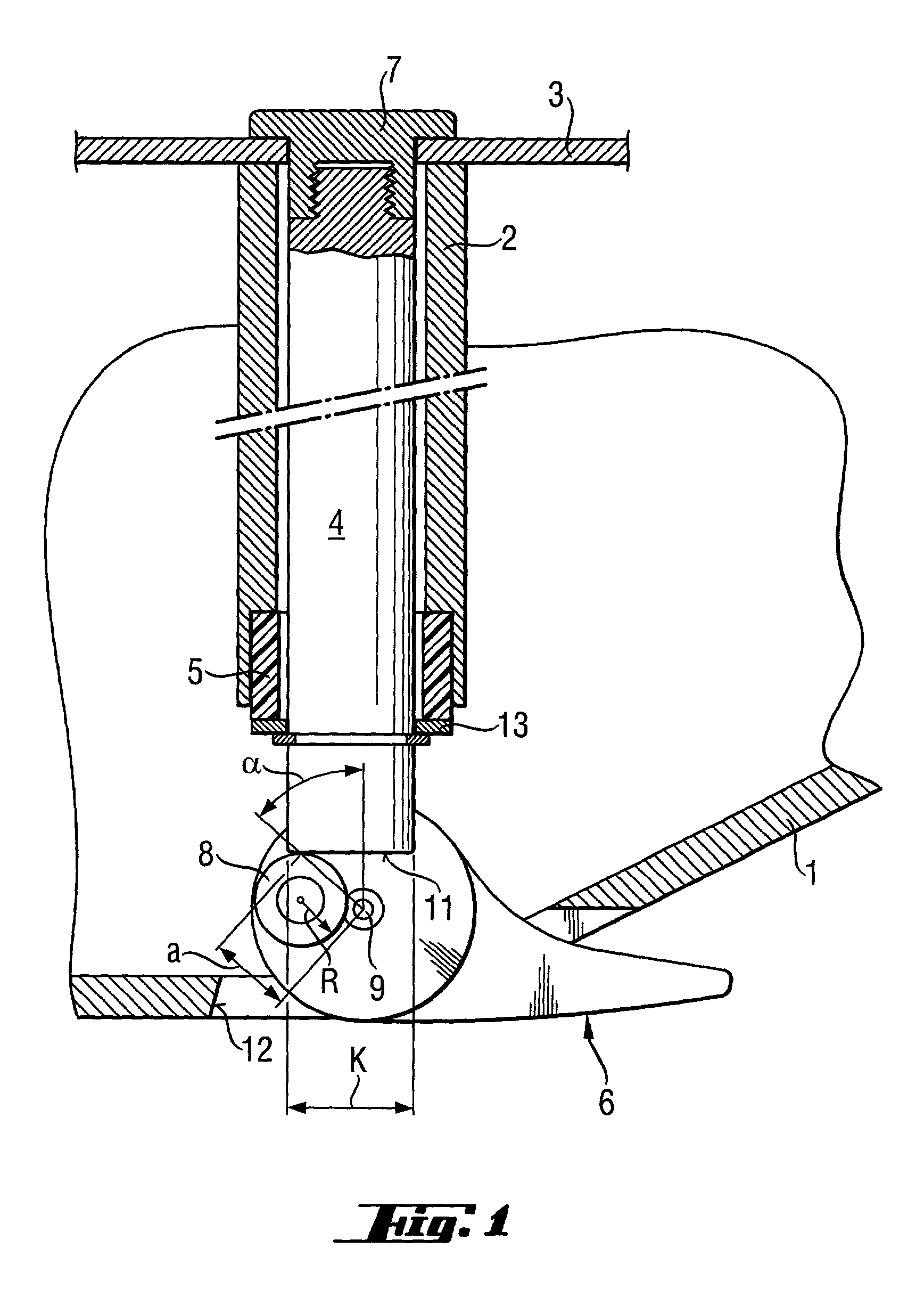
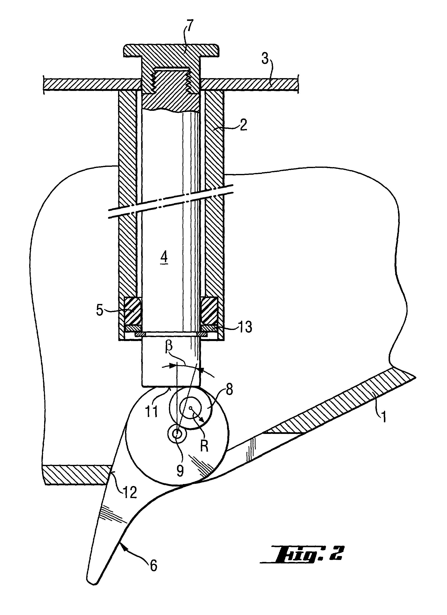
[0022]A quick-action locking device for an electrical power tool according to the present invention, which is shown in FIGS. 1–2, is designed for securing a working tool 3 on a hollow, motor-driven spindle 2 located in a housing 1 of the electrical power tool. The quick-action locking device has a locking spindle 4 axially displaceable in the hollow spindle 2 of the power tool. The locking spindle 4 is axially restrained with a resilient member 5. The resilient member 5 is located in a stepped bore formed in the spindle 2 at its end remote from the working tool 3. The resilient member 5 has one of its end supported against a shoulder formed in the stepped bore, and is supported at its opposite end by a flange 13 secured on the locking spindle 4. A locking lever 6, which is secured to the locking spindle 4 at its end remote from the working tool 3, provides for displacement of the quick-action locking device between its locking position which is shown in FIG. 1, and an exchange posit...


PUM

PropertyMeasurementUnit
angleaaaaaaaaaa
angleaaaaaaaaaa
end angleaaaaaaaaaa

Abstract

A quick-action locking device for an electric power tool including a locking spindle (4) axially displaceable in the hollow spindle (2) of the electrical power tool between a working tool locking position and a working tool exchange position, and a locking lever (6) provided at the end of the locking spindle remote from the working tool and having a slider cooperating with the locking spindle (4) for displacing the same, upon a pivotal movement of the locking lever (6), to its tool exchange position, with the slider (8) having a contact region engageable with a contact surface provided at the end of the locking spindle (4) remote from the working tool (3), and with the contact surface of the locking spindle (4) having an extent, in a pivotal direction of the locking lever (6), corresponding to at least the radial distance (a) of the contact region from the pivot axis (9) of the lever multiplied, in the locking position of the locking lever (6), by a sin (α) of an angle formed by a line, which defines the radial distance (a), with a longitudinal axis of the locking spindle (4).

Description

BACKGROUND OF THE INVENTION[0001]1. Field of the Invention[0002]The present invention relates to quick-action locking device for an electric power tool and, in particular, a circular saw and the like, and designed for securing a working tool to a motor-driven hollow spindle located in a housing of the power tool, with the quick-action locking device including a locking spindle axially displaceable in the hollow spindle of the electrical power tool, a resilient member for axially restraining the locking spindle, a locking flange cooperating with the locking spindle for securing the working tool to the hollow spindle for joint rotation therewith, and a locking lever provided at an end of the locking spindle remote from the working tool and pivotable about a pivot axis between a locking position, in which the working tool is secured to the spindle, and an exchange position in which the working tool can be replaced. The present invention also relates to an electric power tool with a qui...

Claims


Application Information

Patent Timeline
Patent Type & Authority Patents(United States)
IPC IPC(8): B27B5/32B27B5/00B23D61/02B27B9/00
CPCB27B5/32Y10T74/1896Y10T279/16Y10T279/33Y10T403/59Y10T74/20636Y10T83/9403Y10T83/9379Y10T83/9377Y10T83/9464Y10T83/9461
Inventor HARTMANN, MARKUS
Owner HILTI AG
Why Eureka
Try Eureka