Flight guidance and navigation display for a helicopter

a technology for navigation display and flight guidance, which is applied in the direction of navigation instruments, process and machine control, etc., can solve the problems of not providing information, not taking into account, and not yet approving the flight of flight guidance and navigation systems comprising tunnel-in-the-sky displays, so as to reduce workload and be easy to interpret.

Active Publication Date: 2009-11-12
AIRBUS HELICOPTERS DEUT GMBH
View PDF10 Cites 37 Cited by
  • Summary
  • Abstract
  • Description
  • Claims
  • Application Information

AI Technical Summary

Benefits of technology

[0009]In an advantageous manner a flight guidance and navigation display is thus provided which in an advantageous manner provides a pilot not only with information that comprises intuitive visualisation relating to lateral and vertical flight guidance and navigation, but also with intuitively perceptible information about the longitudinal flight guidance and navigation. By way of the command signal, the information necessary for correction is centrally displayed in the pilot's field of vision so that any deviation from the longitudinal flight guidance and navigation can be compensated for right at the beginning by means of an increase or a decrease in speed.
[0010]There is a further advantage in that the flight guidance and navigation tunnel, which according to the invention is semicircular in shape, when compared to the rectangular design known for fixed-wing aircraft comprises less position reference information. Said flight guidance and navigation tunnel according to the invention thus takes into account aerophysical characteristics of the helicopter that are substantially different from those of fixed-wing aircraft. Flight guidance and navigation is thus less restrictive, which to the helicopter pilot signifies a noticeable reduction in the workload.
[0011]According to a particularly advantageous embodiment, a circular reference speed icon with a diameter that corresponds to that of the flight guidance and navigation tunnel is integrated in the flight guidance and navigation tunnel. Corresponding to the reference surface, the reference speed icon also “glides” along the flight guidance and navigation tunnel, wherein the reference speed icon, in contrast to the reference surface, moves at reference speed along the flight guidance and navigation tunnel. Depending on the longitudinal position of the reference speed icon relative to the circular reference surface, the icons, whose diameters are identical, appear to be of different sizes due to the perspective projection. In other words, the deviation between the reference speed icon and the reference surface is a measure of the actual deviation from the predetermined reference speed. This presentation provides an advantage in that the pilot can intuitively estimate the deviation and thus the extent of compensation, and can make corresponding adjustments.
[0012]Preferably, the command signal is in the shape of an arrow, comprising a point. If an increase in the speed is required, the point of the command signal is aligned in the direction of the planned flight path; while if a decrease in the speed is required, the point of the command signal is aligned against the direction of the planned flight path. This presentation has been shown to be particularly advantageous because in this way the pilot is provided with an intuitive presentation of the command to be carried out, which presentation is simple to interpret.

Problems solved by technology

However, even for fixed-wing aircraft, flight guidance and navigation systems comprising tunnel-in-the-sky displays have not yet been approved for instrument flight.
The known three-dimensional flight guidance and navigation displays are associated with a disadvantage in that they do not furnish any information about longitudinal flight guidance and navigation (flight speed / position-time).
There is a further disadvantage in that the known three-dimensional flight guidance and navigation displays were essentially developed for fixed-wing aircraft, and do thus not take into account the aerophysical characteristics of a helicopter.

Method used


Image

  • Flight guidance and navigation display for a helicopter
  • Flight guidance and navigation display for a helicopter
  • Flight guidance and navigation display for a helicopter

Examples


Embodiment Construction

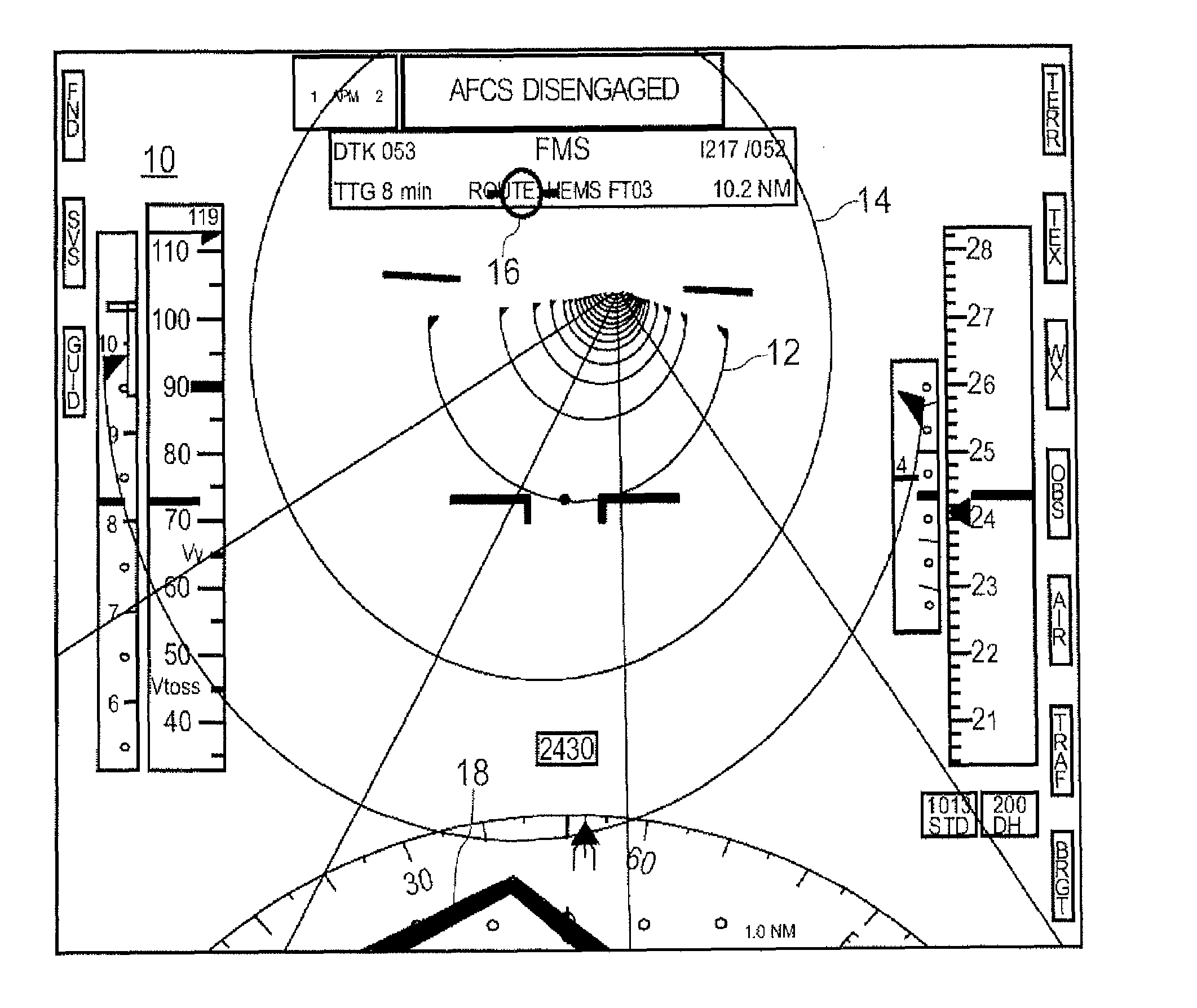
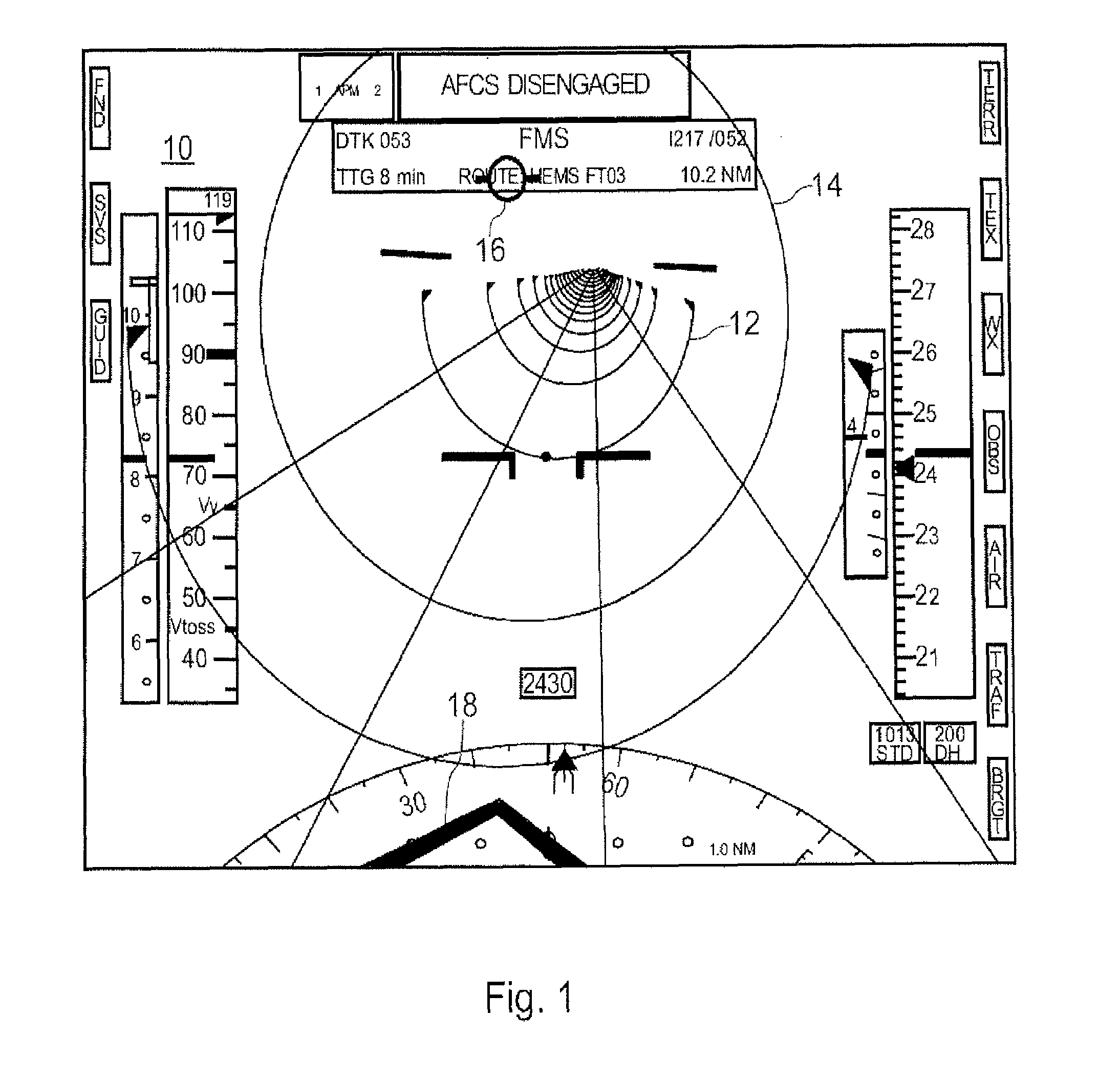
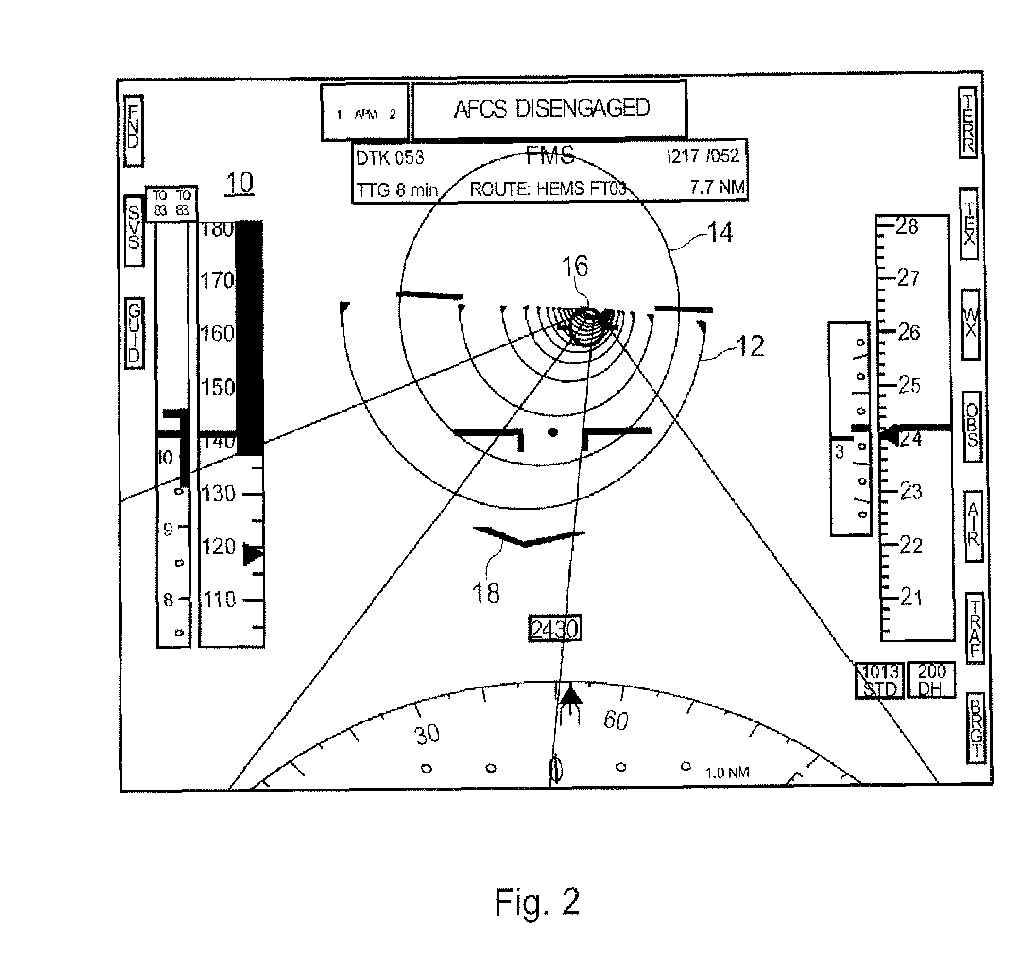
[0021]FIGS. 1 and 2 show a first exemplary embodiment of a flight guidance and navigation display, overall designated 10, for a helicopter.

[0022]As a central display element the flight guidance and navigation display 10 comprises a semicircular three-dimensional flight guidance and navigation tunnel 12 to show a planned flight path of the helicopter in lateral and vertical direction, as well as a circular surface 14, hereinafter also referred to as the reference surface, which circular surface 14 is integrated in the flight guidance and navigation tunnel 12 and comprises a diameter that corresponds to that of the flight guidance and navigation tunnel 12, for displaying a longitudinal position within the flight guidance and navigation tunnel 12. The reference surface 14“glides” through the flight guidance and navigation tunnel 12 at the speed of flight of the helicopter.

[0023]Furthermore, the flight guidance and navigation display 10 comprises a flight path prediction icon 16 that sh...


PUM


Abstract

A flight guidance and navigation display (10) for a helicopter, includes a three-dimensional, semicircular flight guidance and navigation tunnel (12) to display a planned flight path of the helicopter; a circular surface (14), which is integrated in the flight guidance and navigation tunnel (12), which circular surface (14) includes a diameter that corresponds to that of the flight guidance and navigation tunnel (12), for displaying a longitudinal position within the flight guidance and navigation tunnel (12); a flight path prediction icon (16) for displaying a position of the helicopter relative to the flight guidance and navigation tunnel (12); and a command signal (18) that relates to the air speed, wherein via the command signal (18) a deviation from a reference speed that has been predetermined by flight planning is displayed.

Description

[0001]The invention relates to a flight guidance and navigation display for a helicopter, according to the type stated in claim 1.BACKGROUND OF THE INVENTION[0002]For fixed-wing aircraft, flight guidance and navigation displays with a tunnel-like display of a planned flight path in space, so-called tunnel-in-the-sky displays, are known. However, even for fixed-wing aircraft, flight guidance and navigation systems comprising tunnel-in-the-sky displays have not yet been approved for instrument flight.[0003]Due to their tunnel-like display of the planned flight path, the known flight guidance and navigation displays, hereinafter also referred to as three-dimensional flight guidance and navigation displays, provide information on lateral (heading) and vertical (flight altitude) guidance that comprises intuitive visualisation for the pilot. The known three-dimensional flight guidance and navigation displays are associated with a disadvantage in that they do not furnish any information ab...

Claims


Application Information

Patent Timeline
Patent Type & Authority Applications(United States)
IPC IPC(8): G05D1/00
CPCG01C23/005
Inventor SPEK, JORRIT VAN DER
Owner AIRBUS HELICOPTERS DEUT GMBH
Why Eureka
Try Eureka