

Mobile communications system, mobile station and base station
- Summary
- Abstract
- Description
- Claims
- Application Information
AI Technical Summary
Benefits of technology
Problems solved by technology
Method used
Image


Examples
first preferred embodiment
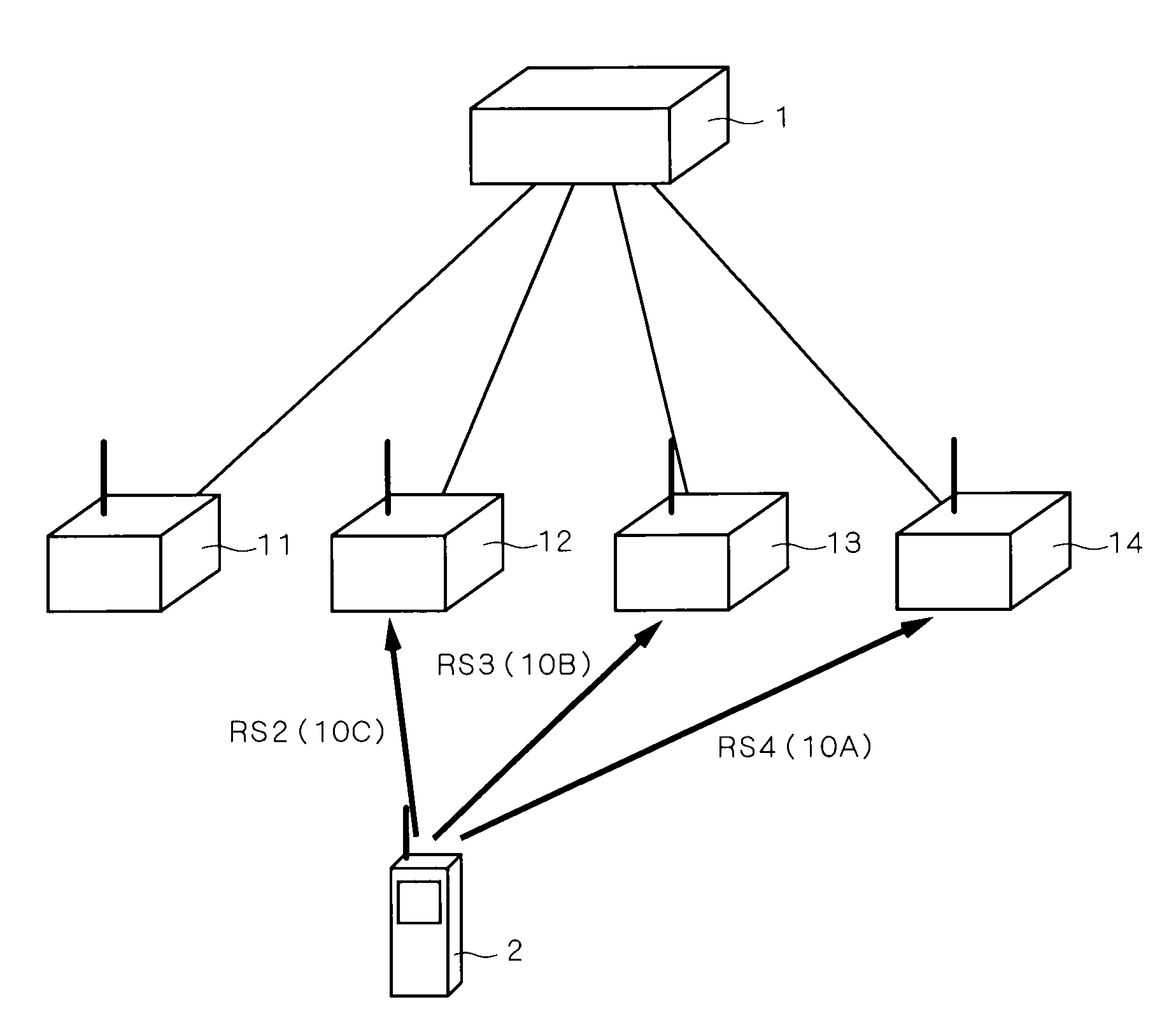
[0075]FIG. 1 is a diagram illustrating the configuration of a mobile communications system according to a first preferred embodiment of the present invention. As shown in the diagram, this system has a network configuration in which a plurality of base stations 11 to 14 are connected to a base station host apparatus 1 including a core network, base station control apparatus, and the like, where a mobile station (terminal) 2 is capable of communicating simultaneously with a plurality of base stations among the base stations 11 to 14.
[0076]In FIG. 1, the base station host apparatus 1 is connected to the plurality of base stations 11 to 14, and sends / receives control signals to and from the base stations, so as to control the base stations 11 to 14 and to simultaneously distribute the same data to the multiple base stations 11 to 14 connected thereto. The base stations 11 to 14 each have a function of communicating with the mobile station 2 by radio. In FIG. 1, the base station 11 is n...
second preferred embodiment
[0209]FIG. 19 is a diagram illustrating a condition of communication in a mobile communications system according to a second preferred embodiment of the present invention. In the mobile communications system shown in the diagram, a mobile station 6 is capable of communicating by radio simultaneously with a plurality of base stations 51 to 53.
[0210]The mobile communications system of the second preferred embodiment differs from that of the first preferred embodiment in that a response including resource-related information RJ is sent back in response to a request from a mobile station, without using broadcast information using broadcast channels. That is, when a base station receives a request from one mobile station for the conditions of resources etc. (resource request), it then sends resource-related information including the conditions of resources etc. as a response back to the one mobile station (resource response). Each base station thus gives a resource response to each mobil...
third preferred embodiment
[0253]FIG. 26 is a diagram illustrating the configuration of a mobile communications system according to a third preferred embodiment of the present invention. The diagram (a) shows a normal condition, and the diagram (b) shows a condition in which some line is unstable.
[0254]As shown in the diagrams, like the configuration of the first preferred embodiment shown in FIG. 1, the mobile communications system of the third preferred embodiment has a network composed of base stations 71 to 74 and a base station host apparatus 7 connected to all base stations 71 to 74, and a mobile station 8 can communicate simultaneously with the multiple base stations 71 to 74.
[0255]In FIG. 26, the mobile station (terminal) 8 is communicating simultaneously with all base stations 71 to 74. Also, as in the configuration of FIG. 16, the mobile station 8 is sending / receiving different data respectively with the base stations 71 to 74. For example, the mobile station 8 is sending data D to the base station ...
PUM
 Abstract
Description
Claims
Application Information