Super-turbocharger having a high speed traction drive and a continuously variable transmission

a technology of traction drive and transmission, which is applied in the direction of friction gearing, combustion engines, gearing, etc., can solve the problem that the turbocharger produces inadequate boost for proper engine transient respons

Inactive Publication Date: 2010-02-11
VANDYNE SUPERTURBO
View PDF81 Cites 73 Cited by
  • Summary
  • Abstract
  • Description
  • Claims
  • Application Information

AI Technical Summary

Problems solved by technology

However, at lower speeds, the turbocharger produces inadequate boost for proper engine transient response.

Method used


Image

  • Super-turbocharger having a high speed traction drive and a continuously variable transmission
  • Super-turbocharger having a high speed traction drive and a continuously variable transmission
  • Super-turbocharger having a high speed traction drive and a continuously variable transmission

Examples


Embodiment Construction

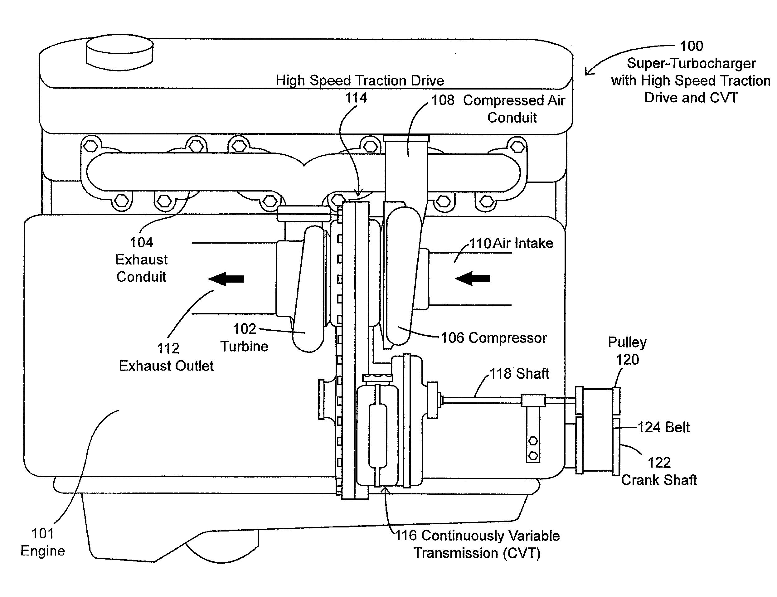
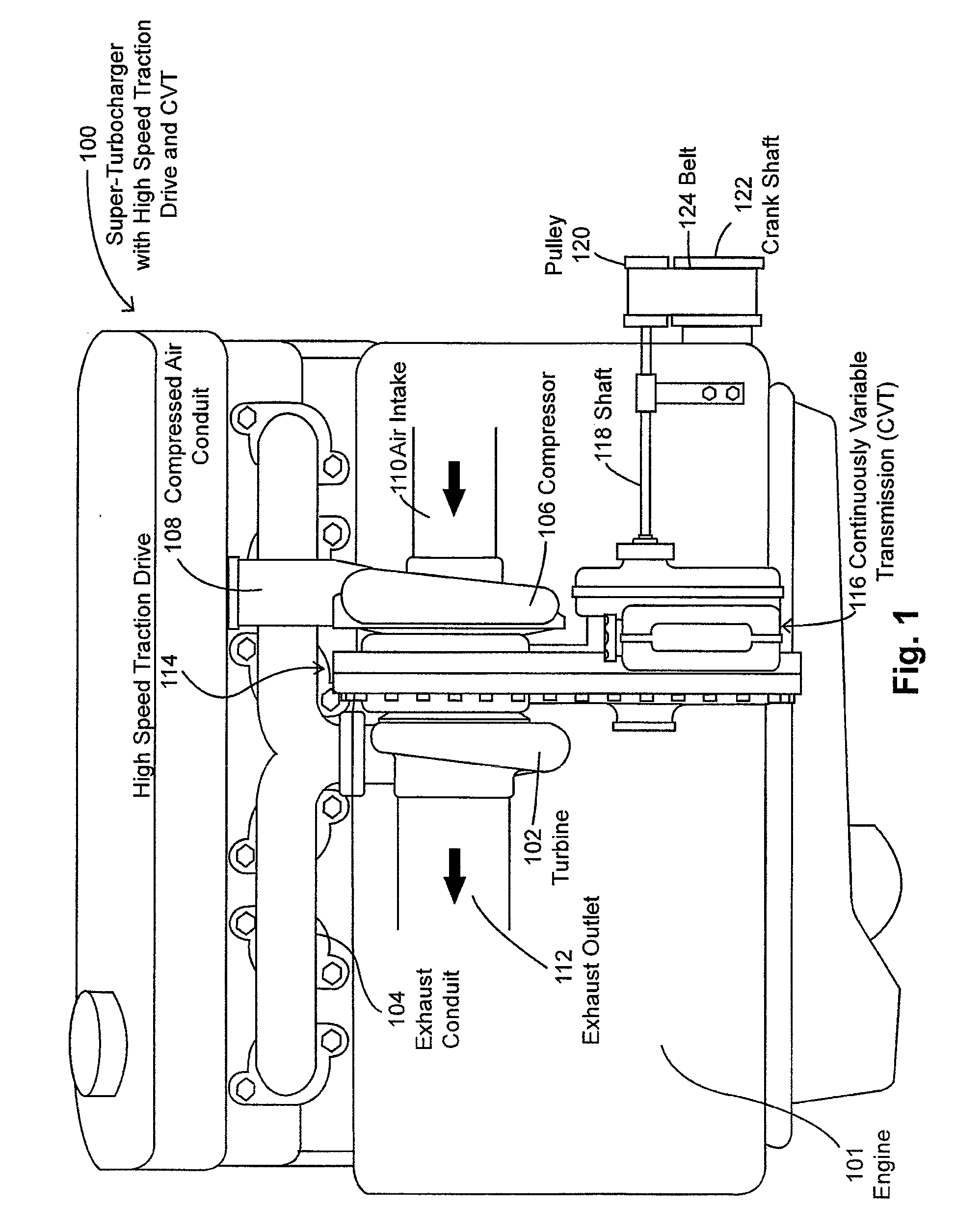
[0016]FIG. 1 is a schematic illustration of an embodiment of a super-turbocharger 100 that uses a high speed traction drive 114 and a continuously variable transmission 116. As shown in FIG. 1, the super-turbocharger 100 is coupled to the engine 101. The super-turbocharger includes a turbine 102 which is coupled to engine 101 by an exhaust conduit 104. The turbine 102 receives the hot exhaust gases from the exhaust conduit 104 and generates rotational mechanical energy prior to exhausting the exhaust gases in an exhaust outlet 112. A catalytic converter (not shown) can be connected between the exhaust conduit 104 and turbine 102. Alternatively, the catalytic converter (not shown) can be connected to the exhaust outlet 112. The rotational mechanical energy generated by the turbine 102 is transferred to the compressor 106 via a turbine / compressor shaft, such as shaft 414 of FIG. 4, to rotate a compressor fan disposed in the compressor 106, which compresses the air intake 110 and trans...


PUM


Abstract

A super-turbocharger utilizing a high speed, fixed ratio traction drive that is coupled to a continuously variable transmission to allow for high speed operation is provided. A high speed traction drive is utilized to provide speed reduction from the high speed turbine shaft. A second traction drive provides infinitely variable speed ratios through a continuously variable transmission.

Description

CROSS-REFERENCE TO RELATED APPLICATION[0001]This patent application claims the benefit of U.S. Provisional Patent Application Ser. No. 61 / 086,401, filed Aug. 5, 2008, the entire teachings and disclosure of which are incorporated by reference thereto.BACKGROUND OF THE INVENTION[0002]Conventional turbochargers are driven by waste exhaust heat and gases, which are forced through an exhaust turbine housing onto a turbine wheel. The turbine wheel is connected by a common turbo-shaft to a compressor wheel. As the exhaust gases hit the turbine wheel, both wheels simultaneously rotate. Rotation of the compressor wheel draws air in through a compressor housing, which forces compressed air into the engine cylinder to achieve improved engine performance and fuel efficiency. Turbochargers for variable speed / load applications are typically sized for maximum efficiency at torque peak speed in order to develop sufficient boost to reach peak torque. However, at lower speeds, the turbocharger produc...

Claims


Application Information

Patent Timeline
Patent Type & Authority Applications(United States)
IPC IPC(8): F02B33/00F16H15/04F16H13/08F16H15/50
CPCF02B37/105F02B39/04F02B41/10F16H9/16Y02T10/163F16H15/04F16H15/50Y02T10/144F16H13/06Y02T10/12
Inventor VANDYNE, EDBRINKS, BARRY T.RILEY, MICHAEL B.
Owner VANDYNE SUPERTURBO
Why Eureka
Try Eureka