Flush-Mounted Flashing Light

a flush-mounted flashing light and flashing light technology, which is applied in the direction of lighting protection devices, lighting heating/cooling arrangements, lighting applications, etc., can solve the problems of neither the flush-mounted flashing light itself nor the aircraft undercarriage being damaged, so as to prolong the life of the flush-mounted flashing light, prevent overheating of components, and design compact

Active Publication Date: 2010-03-04
ADB SAFEGATE BVBA
View PDF8 Cites 10 Cited by
  • Summary
  • Abstract
  • Description
  • Claims
  • Application Information

AI Technical Summary

Benefits of technology

[0009]According to the invention, the object is achieved for example by a flush-mounted flashing light of the type mentioned initially. Since an elongated light source is used, designed to emit light over a length of less than 100 mm, smaller diameters can be used for the housing pot. Since a lens for focusing of the light which is emitted from the light source is arranged on a light inlet surface of the prism, it is possible to design the lens / prism combination according to the invention to be smaller than the prisms which are known from the prior art. The light flashes from the high-light-intensity and relatively short light source are gathered by the lens arrangement and emitted with low losses in a predetermined emission direction by using the prism to vary the direction. The relatively small lens / prism combination makes it possible to reduce the size of the light outlet openings in the housing cover which in turn leads to a reduction in the projection above ground level. In addition to the reduction of the projection, the smaller design—in particular the lens / prism combination as well—results in a reduction in the total weight of the flush-mounted flashing light according to the invention. This makes it possible for the flush-mounted flashing light according to the invention to be carried by just one person, thus simplifying and reducing the cost of installation and maintenance efforts. The reduction in size furthermore allows applications which previously were not possible, for example installations embedded in a flat ground surface.
[0011]In one preferred refinement of the flush-mounted flashing light according to the invention, the lens and the prism are formed integrally, with the lens being integrally formed directly on the light inlet surface of the prism. This makes it possible to achieve two functions, specifically light focusing and beam direction changing, by a single component. In addition to manufacturing advantages, it is also possible to install one item more easily than two separate components, which would need to be held separately and adjusted with respect to one another. The combined lens / prism arrangement is, furthermore, more compact and is thus also lighter in weight, since this glass module contributes significantly to the total weight of the flush-mounted flashing light. In one preferred embodiment of the flush-mounted flashing light according to the invention, the maximum projection caused by the light outlet openings in the housing cover is 18 mm. The use of the compact lens / prism combination makes it possible to reduce the size of the light outlet openings in the housing cover. This allows a housing cover design whose projection above ground level does not exceed 18 mm. This in turn improves the behavior when aircraft roll over it as they are presented with a smaller obstruction.
[0012]In another preferred refinement of the flush-mounted flashing light according to the invention, a drive circuit for controlled production of light flashes is arranged in the housing. An internal drive such as this allows longer cable paths between the flashing light and the associated ballast, from where the drive has until now had to be provided, thus limiting the cable length.
[0014]In a further advantageous embodiment of the flush-mounted flashing light according to the invention, the housing cover and the housing pot are each formed integrally. This reduces the number of components of the flush-mounted flashing light according to the invention thus considerably simplifying assembly before initial installation, as well as after maintenance, thus reducing the production and maintenance costs.
[0016]In another preferred refinement of the flush-mounted flashing light according to the invention, cooling ribs are integrally formed on the housing pot. As a result of the more compact design, this allows the thermal energy that is emitted during the light flashes to be dissipated to the exterior from the housing. This prevents overheating of components and thus lengthens the life of a flush-mounted flashing light according to the invention.

Problems solved by technology

The loads which occur as a result of normal modern aircraft types landing on them, rolling over them or static loads should cause damage neither to the flush-mounted flashing light itself nor to aircraft undercarriages.

Method used


Image

  • Flush-Mounted Flashing Light
  • Flush-Mounted Flashing Light
  • Flush-Mounted Flashing Light

Examples


Embodiment Construction

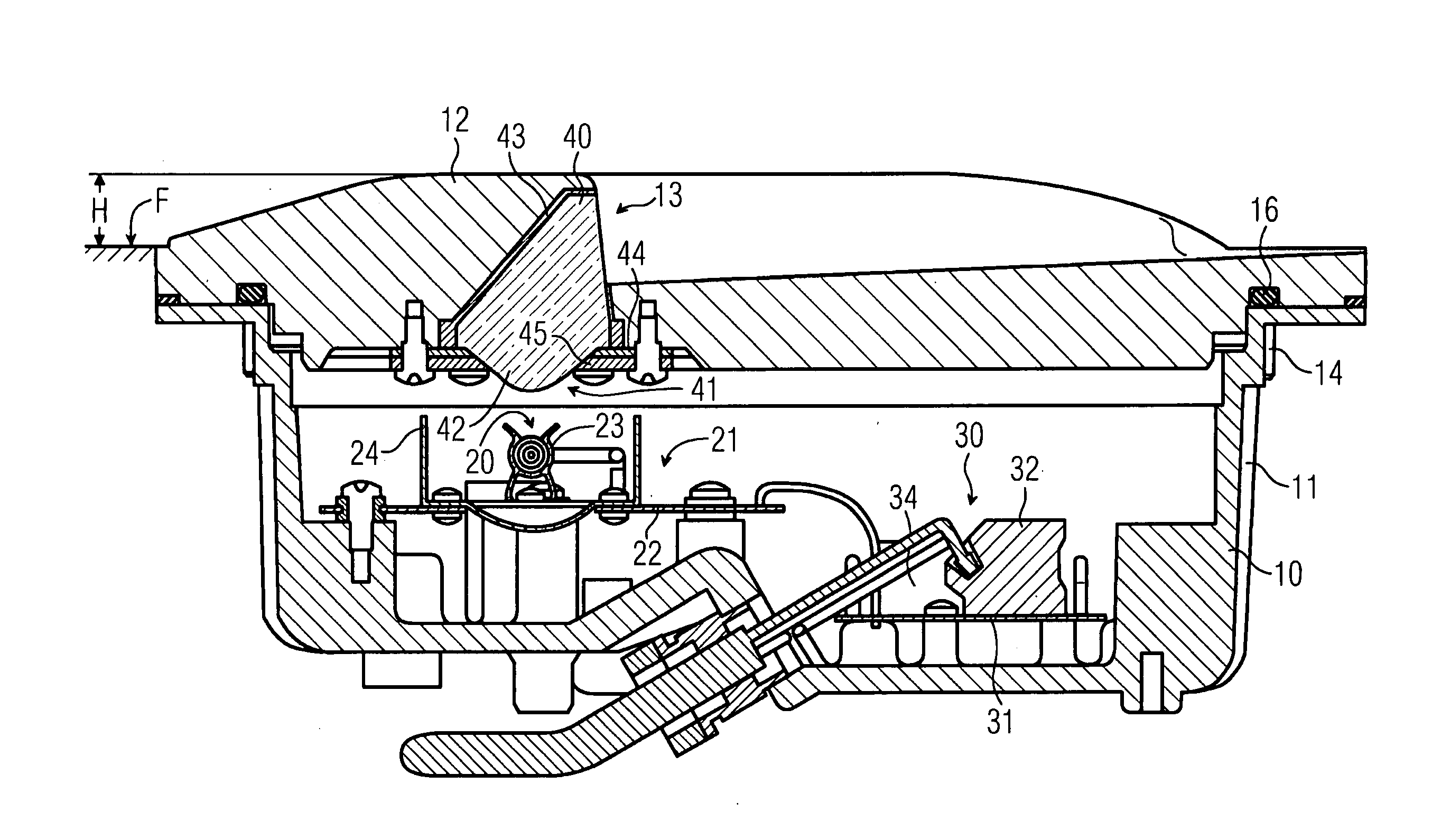
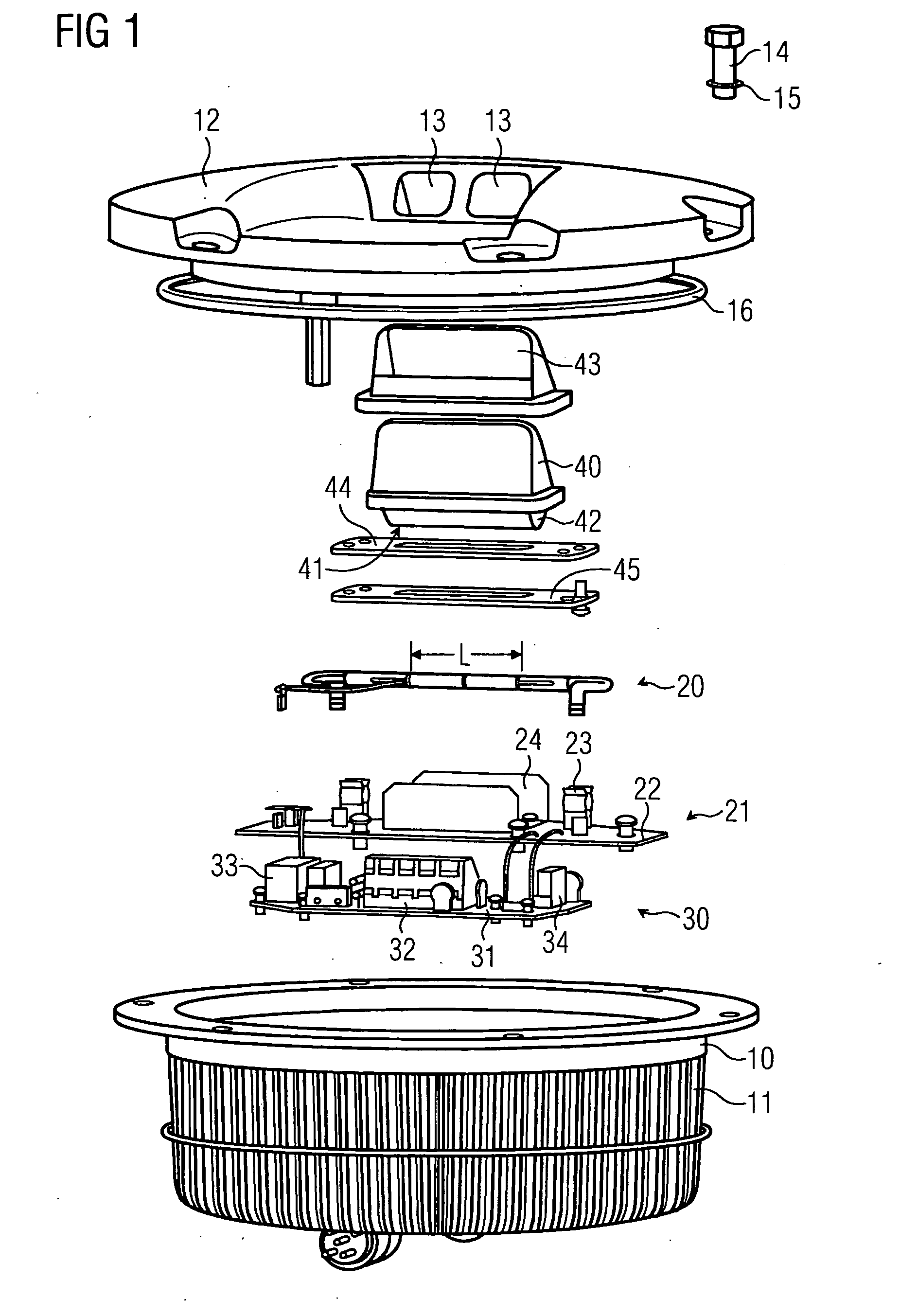
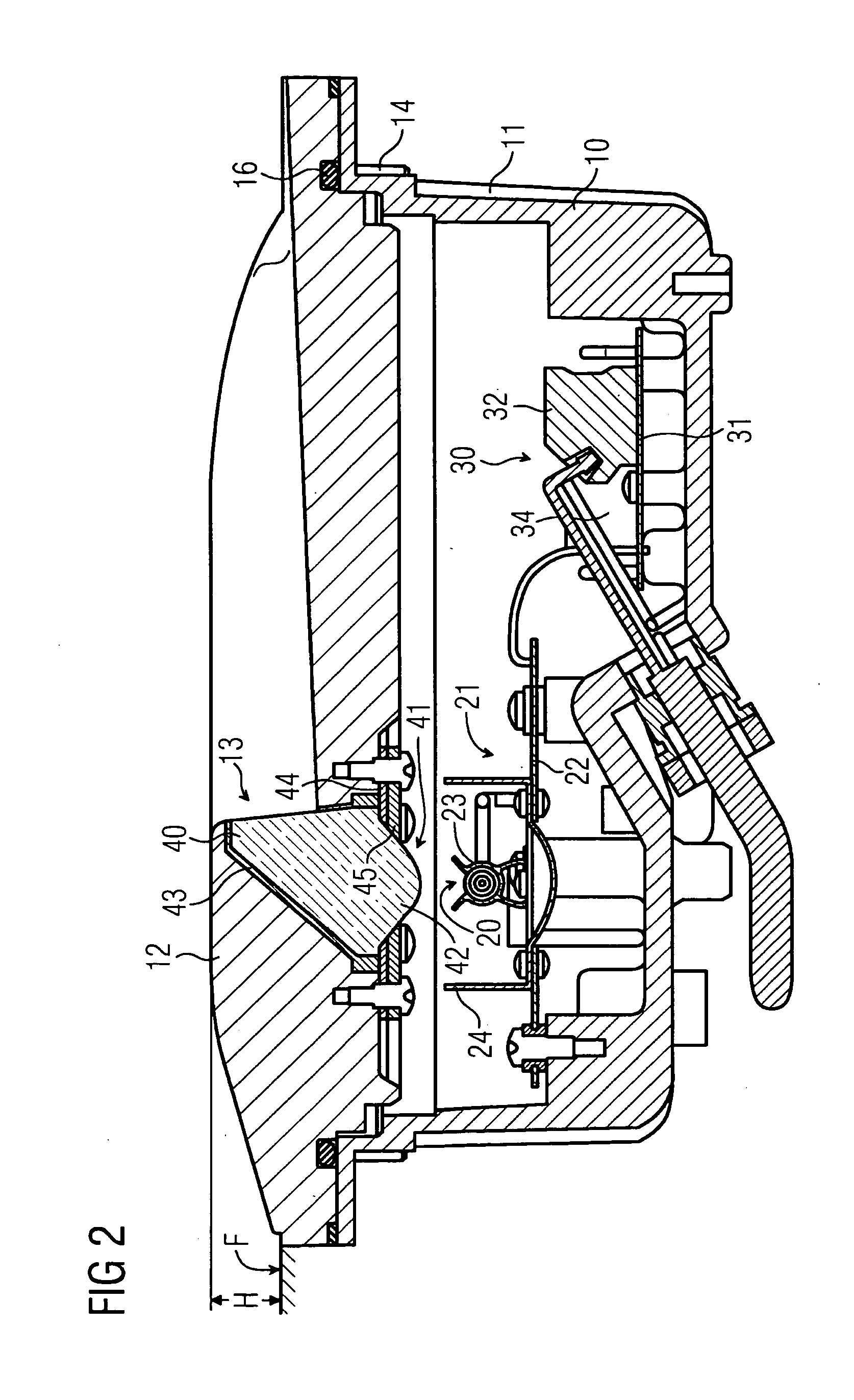
[0020]A flush-mounted flashing light according to the invention for aircraft approach guidance to airports has a closed housing, as shown in FIG. 1 and FIG. 2. The housing comprises a housing pot 10 which can be inserted into a built-in pot, which is not illustrated but is arranged in the ground. A flange to which a housing cover 12 in the form of a plate can be fitted and can be secured by means of screws 14 and spring washers 15 is integrally formed on the upper edge of the housing pot 10. In order to seal the housing interior, a O sealing ring 16 is arranged on the housing pot 10 in the area of the contact surface with the housing cover 12. After installation of the flush-mounted flashing light in the field, the housing cover 12 is arranged approximately at ground level F, with a certain amount of projection H above ground level F.

[0021]An optical system for controlled production and directed emission of light flashes is arranged in the housing of the flush-mounted flashing light...


PUM


Abstract

The invention relates to a flush-mounted flashing light for approach guidance of aircraft, having a housing which has a housing pot (10) which can be inserted below ground level (F) and a housing cover (12) which covers this approximately at ground level (F) and having an optical system, which is arranged in the housing for controlled production and directed emission of light flashes, which comprises a light source (20) for production of light flashes and a prism (40) for varying the direction of the beam direction of the light flashes, with at least one light outlet opening (13) being provided in the housing cover (12) for light flashes to emerge from in a predetermined emission direction. The external dimensions as well as the total weight of the flashing light can be reduced considerably because the light source (20) is elongated and designed to emit a light over a length (L) of less than 100 mm, and because a lens (42) for focusing the light which is emitted from the light source (20) is arranged on a light inlet surface (41) of the prism (40).

Description

CROSS REFERENCE TO RELATED APPLICATIONS[0001]This application is the US National Stage of International Application No. PCT / EP2006 / 067177, filed Oct. 9, 2006 and claims the benefit thereof. The International Application claims the benefits of German application No. 10 2005 048 907.9 DE filed Oct. 10, 2005, both of the applications are incorporated by reference herein in their entirety.FIELD OF INVENTION[0002]The invention relates to a flush-mounted flashing light for approach guidance for aircraft.BACKGROUND OF INVENTION[0003]Flashing lights are used as additional approach and threshold identification lights at airports in poor weather conditions, when the effect of the normal approach lighting is not sufficient to guarantee good, visual approach guidance. However, it may also be expedient to additionally use flashing lights in good visibility conditions, for example in order to make it easier to find the runway in urban areas.[0004]Flashing lights are used in precision approach lig...

Claims


Application Information

Patent Timeline
Patent Type & Authority Applications(United States)
IPC IPC(8): F21V21/00F21V23/00F21V29/00F21V13/02
CPCB64F1/20B64F1/205F21V5/00F21V5/02F21Y2103/00F21V15/01F21W2111/00F21W2111/06F21V5/04
Inventor LAENEN, GUYVANDEREN, MICHELVANDEVOORDE, JEAN-CLAUDEVILLEMS, LOUIS
Owner ADB SAFEGATE BVBA
Why Eureka
Try Eureka