

Flex-Fuel Injector for Gas Turbines
a technology of gas turbines and fuel injectors, which is applied in the direction of combustion process, burners, hot gas positive displacement engine plants, etc., can solve the problem of inadequately addressed criteria
- Summary
- Abstract
- Description
- Claims
- Application Information
AI Technical Summary
Benefits of technology
Problems solved by technology
Method used
Image

Examples
second embodiment
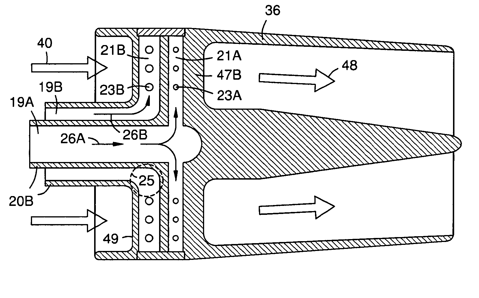
[0030]FIGS. 7 and 8 illustrate aspects of the invention. A first fuel supply channel 19A provides a first fuel 26A to a first radial passage 21A in vanes 47C that extend radially from a fuel delivery tube structure 20B. Alternately, a second fuel supply channel 19B provides a second fuel 26B to second and third radial passages 21C, 21D in the vanes 47C. The fuel delivery tube structure 20B may be formed as concentric tubes as shown, or in another configuration of tubes. Combustion intake air 40 flows over the vanes 47C. The first fuel 26A is injected into the air 40 from first apertures 23A formed between the first radial passages 21A and an exterior surface 49 of the vane. Selectably, the second fuel 26B is injected into the air 40 from second and third sets of apertures 23C, 23D formed between the respective second and third radial passages 21C, 21D and the exterior surface 49 of the vane. The vanes 47C may be shaped to produce turbulence in the fuel / air mixture 48, such as by swi...
third embodiment
[0033]FIG. 9 shows the invention. A first flex-fuel injector vane 47A has a first radial passage 21A and apertures 23A. The first radial passage 21A communicates with a first fuel supply channel as previously described. A second vane 47D has a second radial passage 21E and apertures 23E. The second radial passage 21E communicates with a second fuel supply channel as previously described. The first set of vanes may each comprise a trailing edge 41 that is angled relative to a flow direction 40 of an intake air supply. The second vane 47D may be positioned directly upstream of the first vane 47A. The first and second fuel delivery pathways may differ by at least a factor of two in fuel flow rate at a given backpressure as previously described, thus providing similar features and benefits to the previously described embodiments. Flex-fuel capability is provided for alternate fuels of highly different energy densities, without reducing the area of the intake air flow path between the va...
fourth embodiment
[0035]FIG. 11 illustrates aspects of the invention, in which the arrangement of the fuel supply channels 19A, 19B and the relative positions of the respective radial passages is reversed from previous figures. A first fuel supply channel 19A provides a first fuel 26A to a first radial passage 21A in vanes 47E that extend radially from a fuel delivery tube structure 20C, 20D. Alternately, a second fuel supply channel 19B provides a second fuel 26B to second and third radial passages 21E, 21F in the vanes 47E. The fuel delivery tube structure 20C, 20D may be formed as concentric cylindrical tubes, or in another configuration of tubes. Combustion intake air 40 flows over the vanes 47E. The first fuel 26A is injected into the air 40 from first apertures 23A formed between the first radial passage 21A and an exterior surface 49 of the vanes. Selectably, the second fuel 26B is injected into the air 40 from second and third sets of apertures 23F, 23G formed between the respective second an...
PUM
 Abstract
Description
Claims
Application Information