Multi-panel electronic device

a multi-panel electronic device and electronic device technology, applied in the field of multi-panel electronic devices, can solve the problems of reducing the richness of user's interaction with the portable device, reducing the value of information, and limiting the use of such portable devices

Inactive Publication Date: 2010-04-08
QUALCOMM INC
View PDF69 Cites 352 Cited by
  • Summary
  • Abstract
  • Description
  • Claims
  • Application Information

AI Technical Summary

Benefits of technology

[0005]In a particular embodiment, an electronic device is disclosed that includes multiple folding display panels. When fully extended, the electronic device can provide an extended larger display. When fully folded to a closed position, the electronic device can provide a small form factor and still provide an abbreviated view similar to a cell phone. In general, the multiple folding display panels enable the electronic device to be used as multiple types of devices depending on how the electronic device is folded or configured. By enabling the electronic device to be positioned in multiple foldable configurations, a user of the electronic device may elect to have a small form factor for easy maneuverability and functionality or may elect an expanded, larger form factor for displaying rich content and to enable interaction with one or more software applications via expanded user interfaces.
[0010]One particular advantage provided by at least one of the disclosed embodiments is enabling a user to control (e.g., via or use movement of the device) when a multi-display device “splits” an image along a gap (thereby displaying the entire image in a distorted geometry) and when the multi-display device “hides” a portion of the image corresponding to the gap (thereby preserving the image geometry but not displaying the entire image).

Problems solved by technology

Although such portable devices may support software application, the usefulness of such portable devices is limited by a size of a display screen of the device.
However, smaller display screens limit an amount of content that can be displayed to a user and may therefore reduce a richness of the user's interactions with the portable device.
However, hiding a portion of the image may result in the loss of valuable information (e.g., one or more characters of text).

Method used


Image

  • Multi-panel electronic device
  • Multi-panel electronic device
  • Multi-panel electronic device

Examples


Embodiment Construction

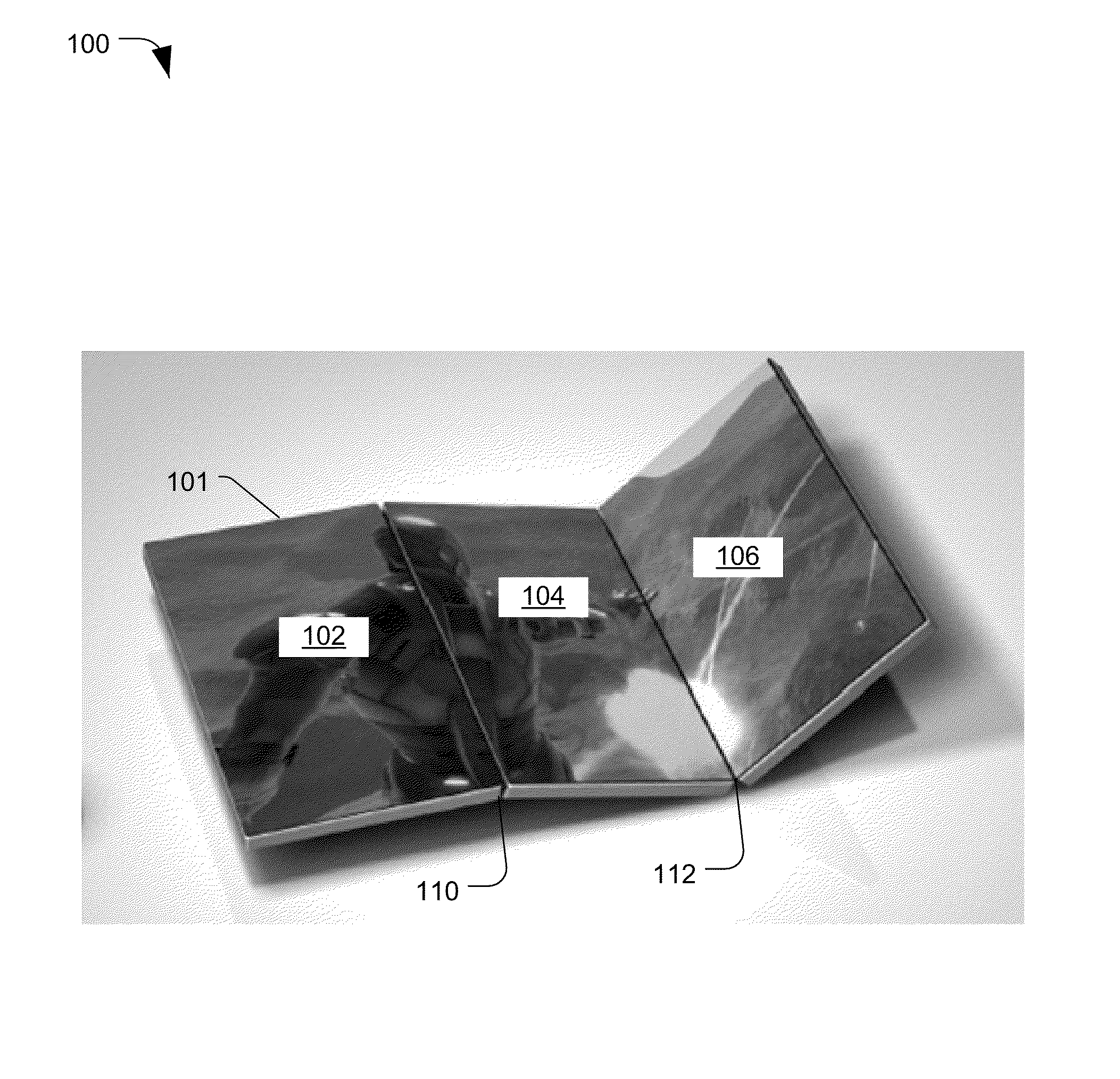
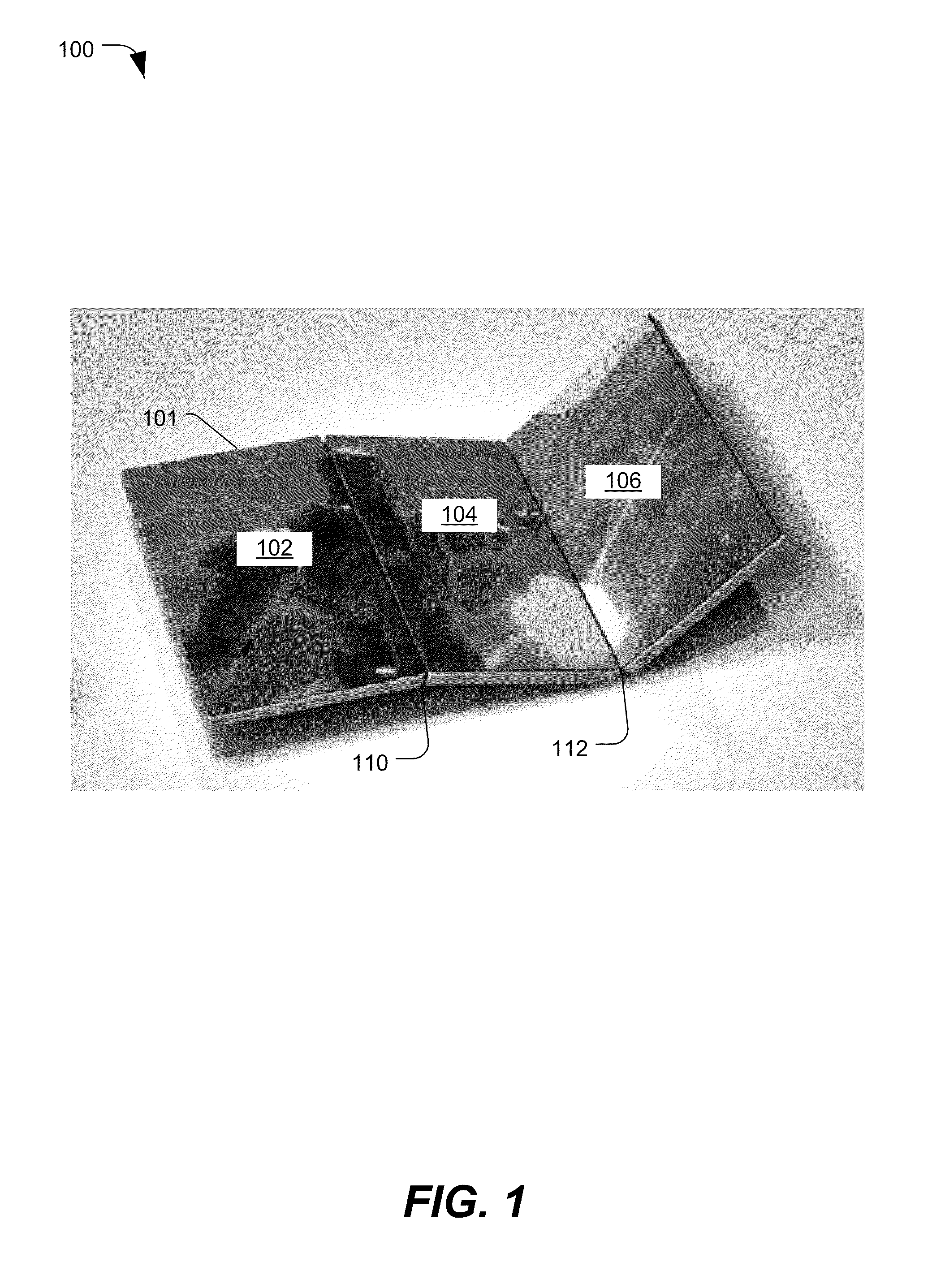
[0081]Referring to FIG. 1, a first illustrated embodiment of an electronic device is depicted and generally designated 100. The electronic device 101 includes a first panel 102, a second panel 104, and a third panel 106. The first panel 102 is coupled to the second panel 104 along a first edge at a first fold location 110. The second panel 104 is coupled to the third panel 106 along a second edge of the second panel 104, at a second fold location 112. Each of the panels 102, 104, and 106 includes a display surface configured to provide a visual display, such as a liquid crystal display (LCD) screen. The electronic device 101 is a wireless communication device having multiple display surfaces and configured to automatically adjust a user interface or to display images when a user changes a physical configuration of the electronic device 101.

[0082]As depicted in FIG. 1 the first panel 102 and the second panel 104 are rotatably coupled at the first fold location 110 to enable a variety...


PUM


Abstract

Methods, apparatuses, and computer-readable storage media for displaying an image at an electronic device are disclosed. In a particular embodiment, a method includes displaying an image at an electronic device that includes a first display surface and a second display surface separated from the first display surface by a gap. A first portion of the image is displayed at the first display surface, a second portion of the image is displayed at the second display surface, and a third portion of the image between the first portion and the second is not displayed. A movement of the electronic device is detected, and in response to detecting the movement, the third portion of the image is displayed at the second display surface.

Description

CROSS-REFERENCE TO RELATED APPLICATIONS[0001]The present disclosure claims the benefit of Provisional Application No. 61 / 095,225, filed Sep. 8, 2008 and 61 / 182,419 filed May 29, 2009, which is incorporated by reference herein in its entirety and to which priority is claimed.FIELD[0002]The present disclosure is generally related to a multi-panel electronic device.DESCRIPTION OF RELATED ART[0003]Advances in technology have resulted in smaller and more powerful computing devices. For example, there currently exist a variety of portable personal computing devices, including wireless computing devices, such as portable wireless telephones, personal digital assistants (PDAs), and paging devices that are small, lightweight, and easily carried by users. More specifically, portable wireless telephones, such as cellular telephones and internet protocol (IP) telephones, can communicate voice and data packets over wireless networks. Further, many such portable wireless telephones include other ...

Claims


Application Information

Patent Timeline
Patent Type & Authority Applications(United States)
IPC IPC(8): G09G5/00G06F3/048G06F3/0484
CPCG06F1/1616H04M2250/16G06F1/1649G06F1/1654G06F1/1677G06F1/1684G06F1/1694G06F3/1431G06F3/1438G06F3/1446G06F3/1454G06F2200/1614G06F2200/1635G09G2300/026H04M1/022H04M1/0247H04M2250/12G06F1/1641
Inventor LUNDQVIST, PATRIK N.DAHL, STEN JORGEN LUDVIG
Owner QUALCOMM INC
Why Eureka
Try Eureka