Control scheme for coordinating variable capacity components of a refrigerant system

a technology of variable capacity and control scheme, which is applied in the field of refrigerant systems, can solve problems such as the difficulty of controlling a refrigerant system

Active Publication Date: 2010-05-06
TRANE INT INC
View PDF9 Cites 42 Cited by
  • Summary
  • Abstract
  • Description
  • Claims
  • Application Information

AI Technical Summary

Benefits of technology

[0006]It is an object of the invention to provide a refrigerant system that can adjust in a coordinated manner the variable capacities of a compressor system, an evaporator fan system and a condenser fan system.
[0007]Another object of some embodiments is to provide a control scheme that minimizes the power consumption of a refrigerant system that includes multiple variable capacity components.
[0008]Another object of some embodiments is to minimize the capacity of a refrigerant system in a prioritized order with the compressor system being first, the evaporator fan system being second, and the condenser fan system being third.
[0010]Another object of some embodiments is to minimize the power consumption of a refrigerant system while maintaining a comfort zone within a target comfort range and maintaining at least a minimum saturated suction temperature of refrigerant leaving the system's condenser.

Problems solved by technology

Although adjusting the capacity of a single component might be relatively straightforward, it can be challenging to control a refrigerant system that includes more than one component of adjustable capacity because varying the capacity of one component can affect the performance of another.

Method used


Image

  • Control scheme for coordinating variable capacity components of a refrigerant system
  • Control scheme for coordinating variable capacity components of a refrigerant system
  • Control scheme for coordinating variable capacity components of a refrigerant system

Examples


Embodiment Construction

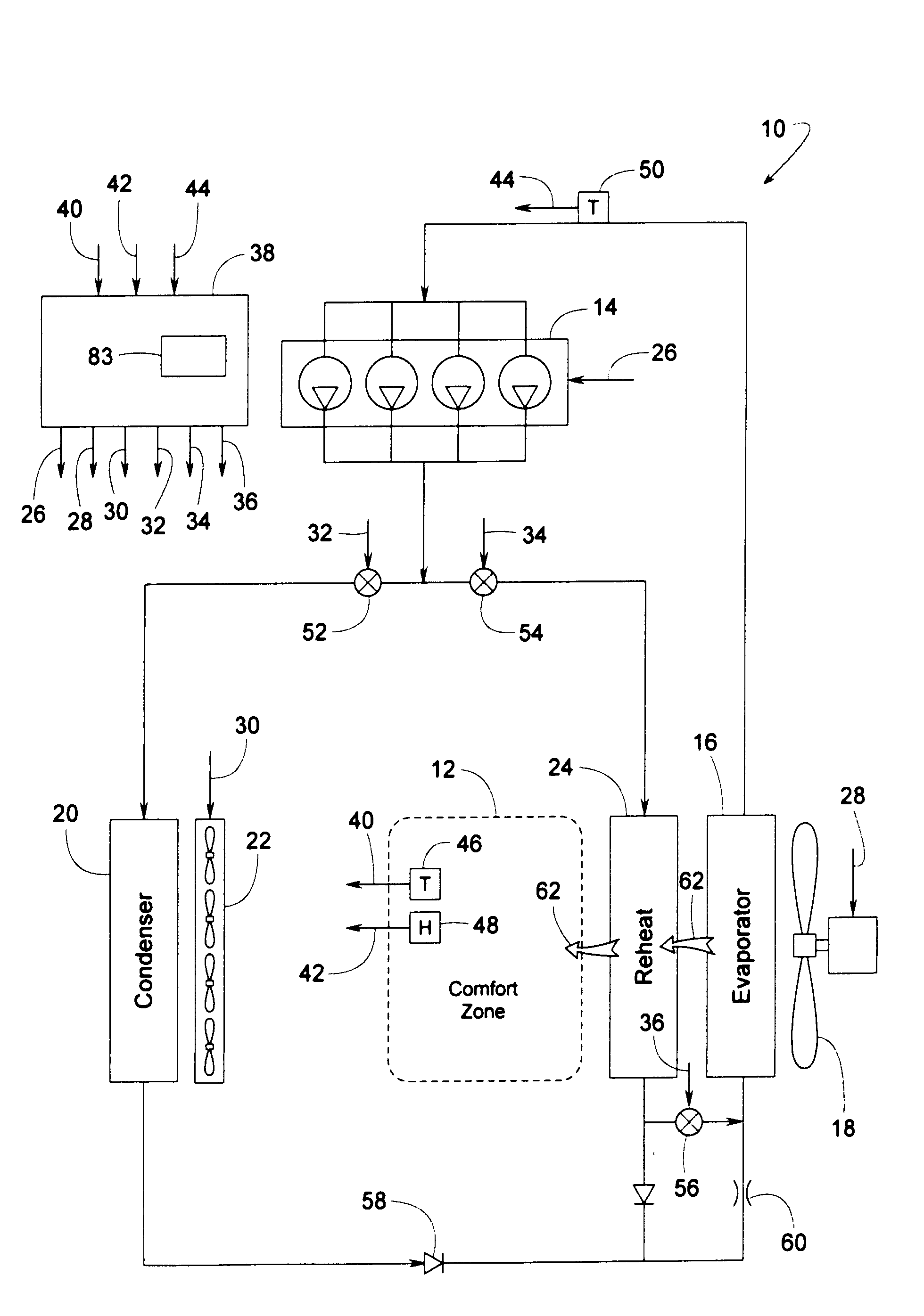
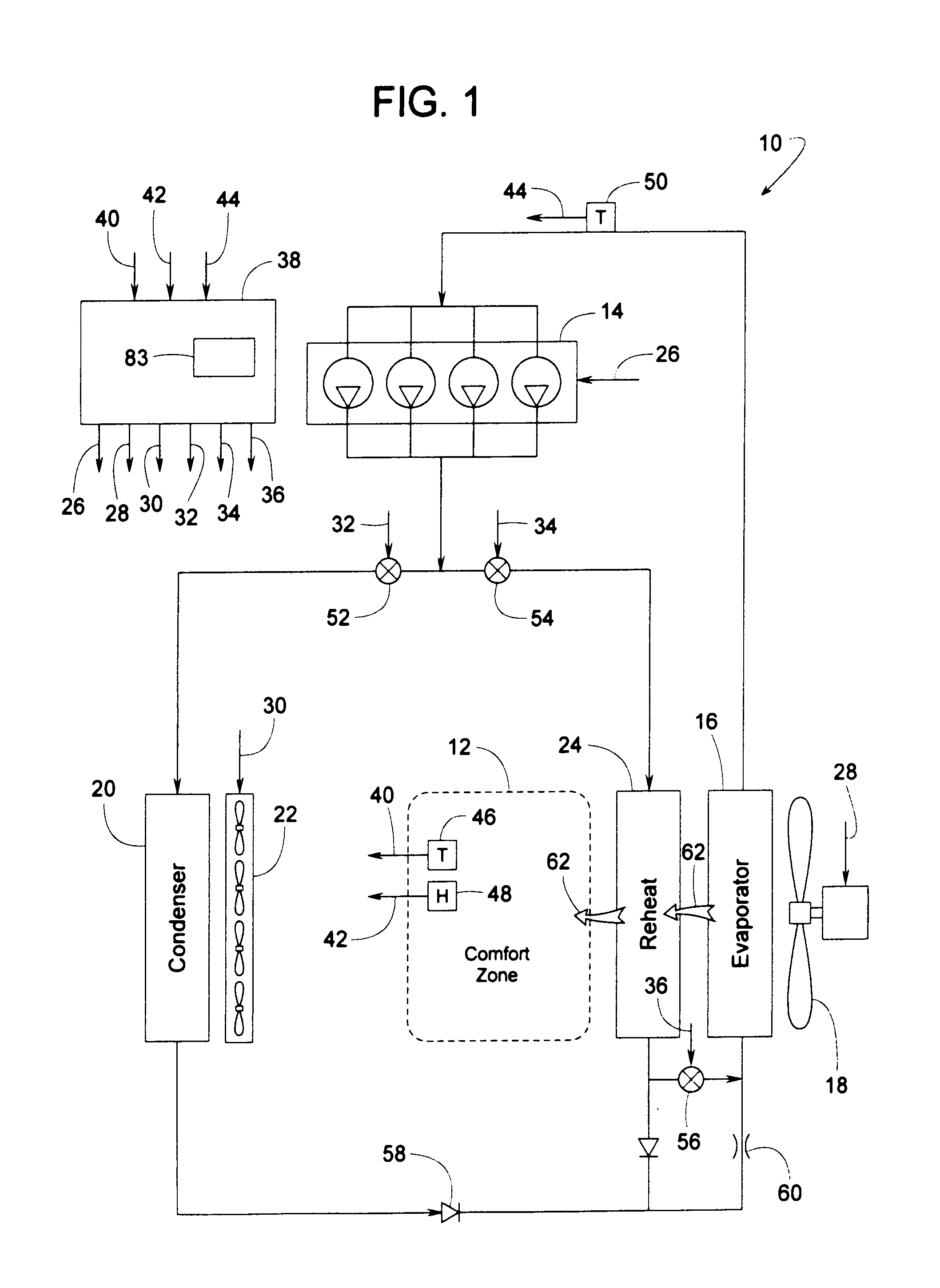
[0015]FIG. 1 schematically illustrates a refrigerant cooling system 10 for controlling the temperature and humidity of a comfort zone 12, such a room or area of a building. To meet the comfort zone's varying demand for cooling or dehumidification, system 10 includes a compressor system 14 with variable compressor capacity (in terms of refrigerant mass flow rate), an evaporator 16 associated with an evaporator fan system 18 with variable evaporator fan capacity (in terms of standard airflow volume across evaporator 16), a condenser 20 associated with a condenser fan system 22 with variable condenser fan capacity (in terms of standard airflow volume across condenser 20), and an optional reheat coil 24 that can be used for heating the cooled air exiting evaporator 16 when system 10 is needed for dehumidifying without sensible cooling.

[0016]It is well known to those of ordinary skill in the art that there are countless ways of varying the operating capacities of individual compressor an...


PUM


Abstract

A refrigerant system adjusts, in a coordinated prioritized manner, the variable capacities of a compressor, evaporator fan and a condenser fan to minimize the system's overall power consumption while maintaining a comfort zone within a target comfort range. The target comfort range is defined by desired temperature and humidity limits. When the comfort zone is within the target comfort range, the system periodically attempts to reduce the compressor capacity. If the attempt succeeds, the evaporator fan capacity is then minimized. The condenser fan capacity can also be minimized provided the refrigerant system can maintain at least a minimum saturated suction temperature of the refrigerant flowing from the condenser to the compressor.

Description

FIELD OF THE INVENTION[0001]The subject invention generally pertains to refrigerant systems and more specifically to a control scheme for adjusting and coordinating the variable capacities of certain system components.BACKGROUND OF RELATED ART[0002]To meet the varying cooling and / or dehumidifying load of a comfort zone, some HVAC refrigerant systems might include a system component of adjustable capacity. Examples of adjustable capacity components include compressors, indoor evaporator fans and outdoor condenser fans.[0003]U.S. Pat. No. 5,303,561 discloses adjusting the indoor fan speed to meet the latent cooling needs of a comfort zone. U.S. Pat. No. 4,590,772 suggests varying the draft volume to a condenser based on the refrigerant pressure therein. U.S. Pat. No. 5,062,276 discloses a refrigerant system where the fan speed is varied linearly with compressor speed, and their speed relationship is altered in response to the need for dehumidification. U.S. Pat. Nos. 5,305,822; 5,345,...

Claims


Application Information

Patent Timeline
Patent Type & Authority Applications(United States)
IPC IPC(8): F25B1/00
CPCF24F3/153F24F11/83F24F11/46F25B49/02F24F11/84F24F11/86
Inventor VOORHIS, ROGER J.SOWADA, PATRICK B.
Owner TRANE INT INC
Why Eureka
Try Eureka