Locking wheel chock

Inactive Publication Date: 2010-05-06
WYERS PHILIP W
View PDF30 Cites 8 Cited by
  • Summary
  • Abstract
  • Description
  • Claims
  • Application Information

AI Technical Summary

Benefits of technology

[0006]It is now proposed, in accordance with the present invention, to eliminate the known wheel lock drawbacks found in the existing prior art, by providing a lo

Problems solved by technology

These prior devices have proposed various solutions relating to the immobilizing of vehicles and trailers with cumbersome locking devices that lack the general strength required, are heavy, or are overly complicated and impractical to use on a regular basis.
These fatal flaws make it disadvantageous for any real practical use or meaningful commercial application.
This device suffers the same drawbacks and limitations as that of Bohler.
Both devices are bulky and lack the innovative design necessary to achieve a practical combination of usability and strength with the fewest amount of required parts.
While this device approaches a usable size, its cumbersome locking mechanism ma

Method used


Image

  • Locking wheel chock
  • Locking wheel chock
  • Locking wheel chock

Examples


Embodiment Construction

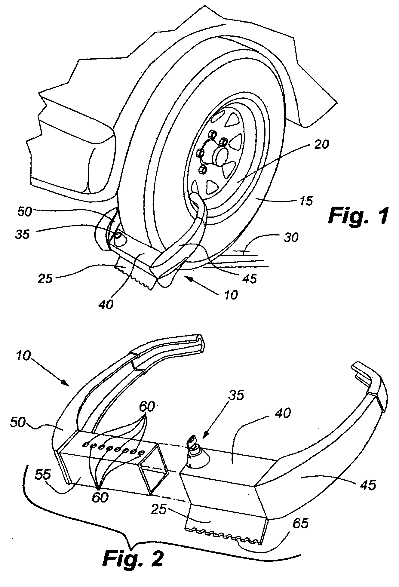
[0018]Referring more particularly to the drawings, wherein like numbers refer to like parts, FIGS. 1 shows the locking wheel chock in the locked and chocked position around a trailer tire 15 and wheel 20. FIG. 1 further shows the chocking engagement of the blade 25 with the ground 30. The relative position of the locking mechanism 35 is shown positioned on the upper surface of the female housing 40 which is attached to a first locking arm 45, which is opposite the second locking arm 50.

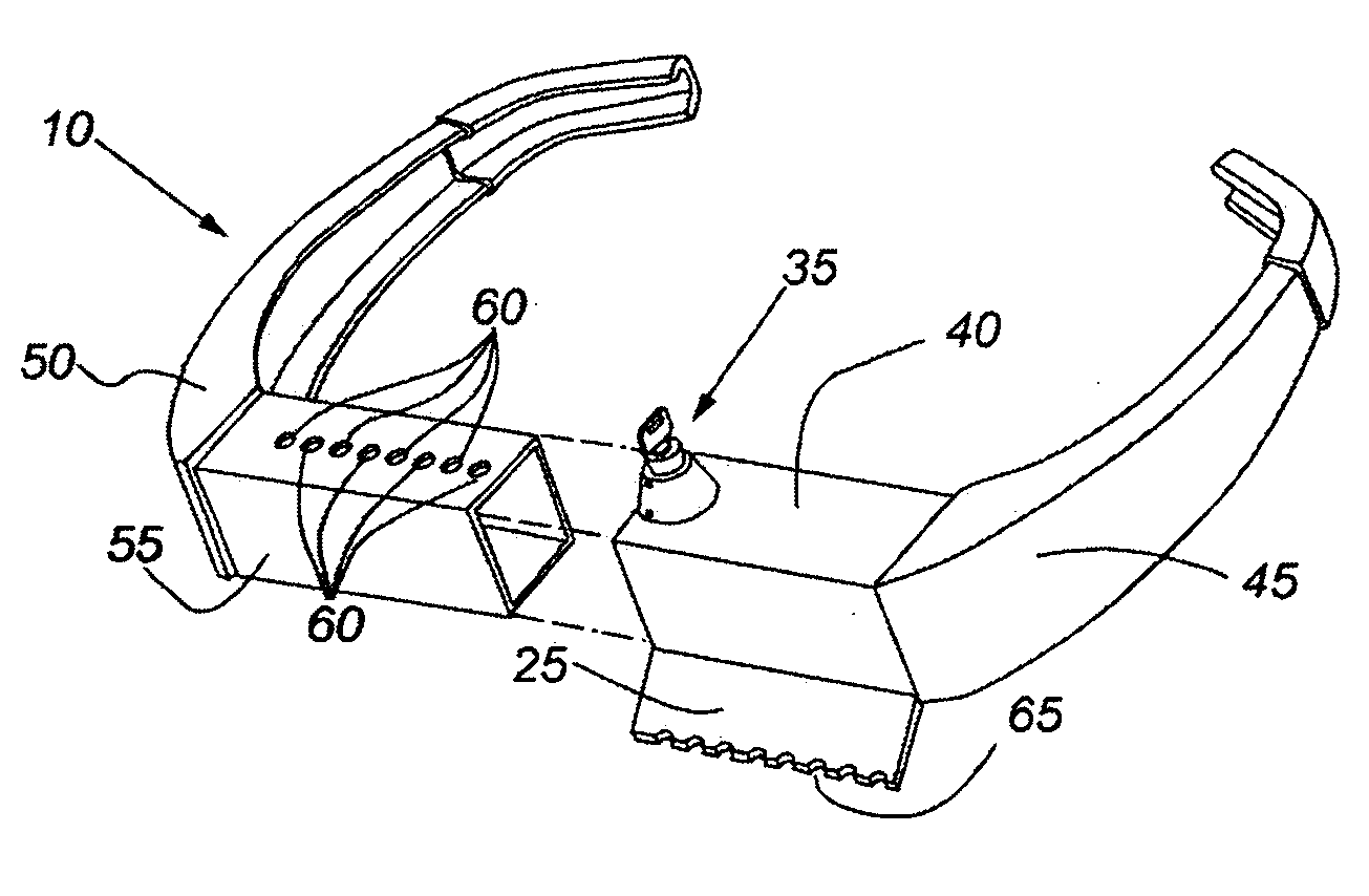
[0019]As shown in FIG. 2 which shows a perspective view of the locking wheel chock 10 in a separated and unlocked state. This view details the male lock housing 55 and shows lock positioning holes 60 that telescopically mate with the female housing and allow for incremental locking engagement with the lock mechanism 35 positioned on the upper surface of the female housing 40. FIG. 2 further shows the first locking arm which is attached to the female housing, and the second locking arm 50 which is atta...


PUM


Abstract

A locking wheel device designed to prevent the unauthorized movement and or roll away of a wheeled vehicle or trailer by locking onto a wheel and having a configuration such that the device also serves to chock the wheel when in the locked on position. A locking wheel chock device which includes two similar matching arms with both a male and female tube attached to one end to allow for the telescopic engagement of said arms. The female tube having attached a lock assembly for locking said arms in a fixed position. Further, the female tube portion has attached to its lower edge, which is closest to the ground, means for contacting the ground in a binding fashion so as to prevent forward rolling movement of the wheel.

Description

FIELD OF THE INVENTION[0001]The present invention relates generally to various wheel chocking apparatus designed to be secured to motor vehicles and or trailer wheels to prevent movement and theft. Devices in the field at present range in complexity from elaborate government style “Denver Boot” (U.S. Pat. No. 2,960,857) type systems to simpler yet lacking in function locking chock type devices like those found in U.S. Pat. No. 3,907,072. These mentioned devices, and all in between fail to adequately address the combined need for strength, convenience and practical security.BACKGROUND ART AND FIELD OF THE INVENTION [0002]The present invention relates to a dramatically improved and simplified embodiment of a lockable wheel chocking device that can be installed quickly and easily to a motor vehicle, unattended trailer, aircraft, or ATV, to name a few. The present invention utilizes non-obvious geometric principles to drastically minimize the size and amount of materials required to eff...

Claims


Application Information

Patent Timeline
IPC IPC(8): B60T3/00E05B35/00B60R25/00
CPCB60R25/093B60T3/00E05B63/0056E05B67/36Y10T70/7486Y10T70/5841
Inventor WYERS, PHILIP W.
Owner WYERS PHILIP W
Why Eureka
Try Eureka