Method, system, and apparatus for highly controlled light distribution from light fixture using multiple light sources (LEDS)

a technology of light source and light source, applied in the field of lighting systems and methods, can solve problems such as optics design, and achieve the effect of easy pre-aiming

Inactive Publication Date: 2010-05-06
MUSCO
View PDF73 Cites 55 Cited by
  • Summary
  • Abstract
  • Description
  • Claims
  • Application Information

AI Technical Summary

Benefits of technology

[0011]Further objects, features, advantages, or aspects of the present invention include the ability to provide illumination of the desired shape, size, and intensity to target areas of a predetermined specification (e.g., corners, walkways, building surfaces, etc.), as well as areas in proximity to “low light zones” (e.g., residences, parks, etc.) using relatively high intensity (high candela produced), high efficiency (high lumens / watt) light sources. Other advantages include the ability to provide an even illumination of a target area that avoids harsh spots (i.e., overly bright spots), shadows, glare, and other undesirable effects.
[0035]Some embodiments of the present invention provide or enhance the ability to pre-aim a fixture at the factory or manufacturer relative to a particular location or application. The envisioned embodiments may be easily pre-aimed, since their placement of light on an area may be accurately established and indexed to the intended mounting positions of the fixtures. Additionally, the fixtures may be aimed precisely in the field by indexing from individually aimed lights / optics or from precision manufactured reference locations on the fixture.

Problems solved by technology

The disadvantage of this approach is that the designed optic may only be used for one type of distribution and requires separate development, tooling, and inventory control for each optic and beam type.

Method used


Image

  • Method, system, and apparatus for highly controlled light distribution from light fixture using multiple light sources (LEDS)
  • Method, system, and apparatus for highly controlled light distribution from light fixture using multiple light sources (LEDS)
  • Method, system, and apparatus for highly controlled light distribution from light fixture using multiple light sources (LEDS)

Examples


Embodiment Construction

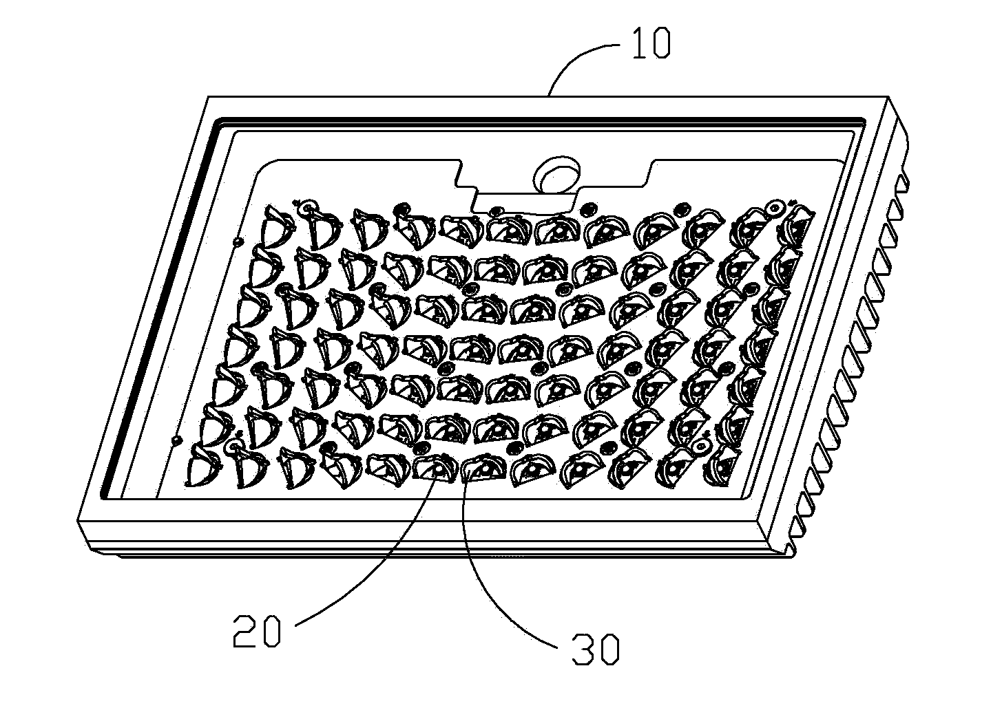
[0072]Aspects according to the present invention provide for apparatus, systems, and methods for creating a composite beam from LEDs (or other light sources) and associated optics such as reflectors or lenses. The composite beam may be comprised of light beams from a single LED fixture (see FIG. 2A), light beams from light sources of multiple LED fixtures that are part of a collective group (see FIG. 2B), and / or light beams from a non-LED (e.g., HID) fixture or fixtures (each of which may use one or more light sources) supplemented by light beams from the envisioned LED fixture(s).

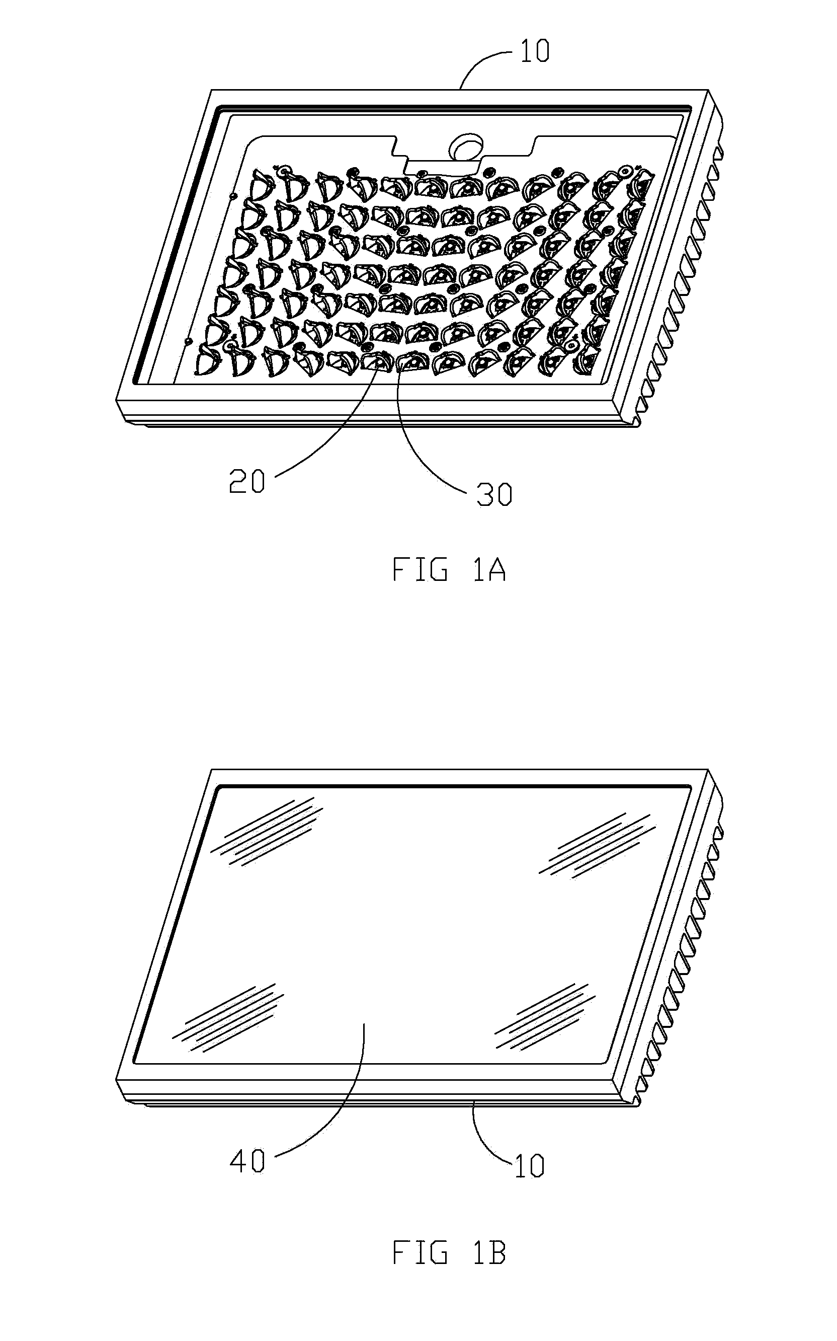
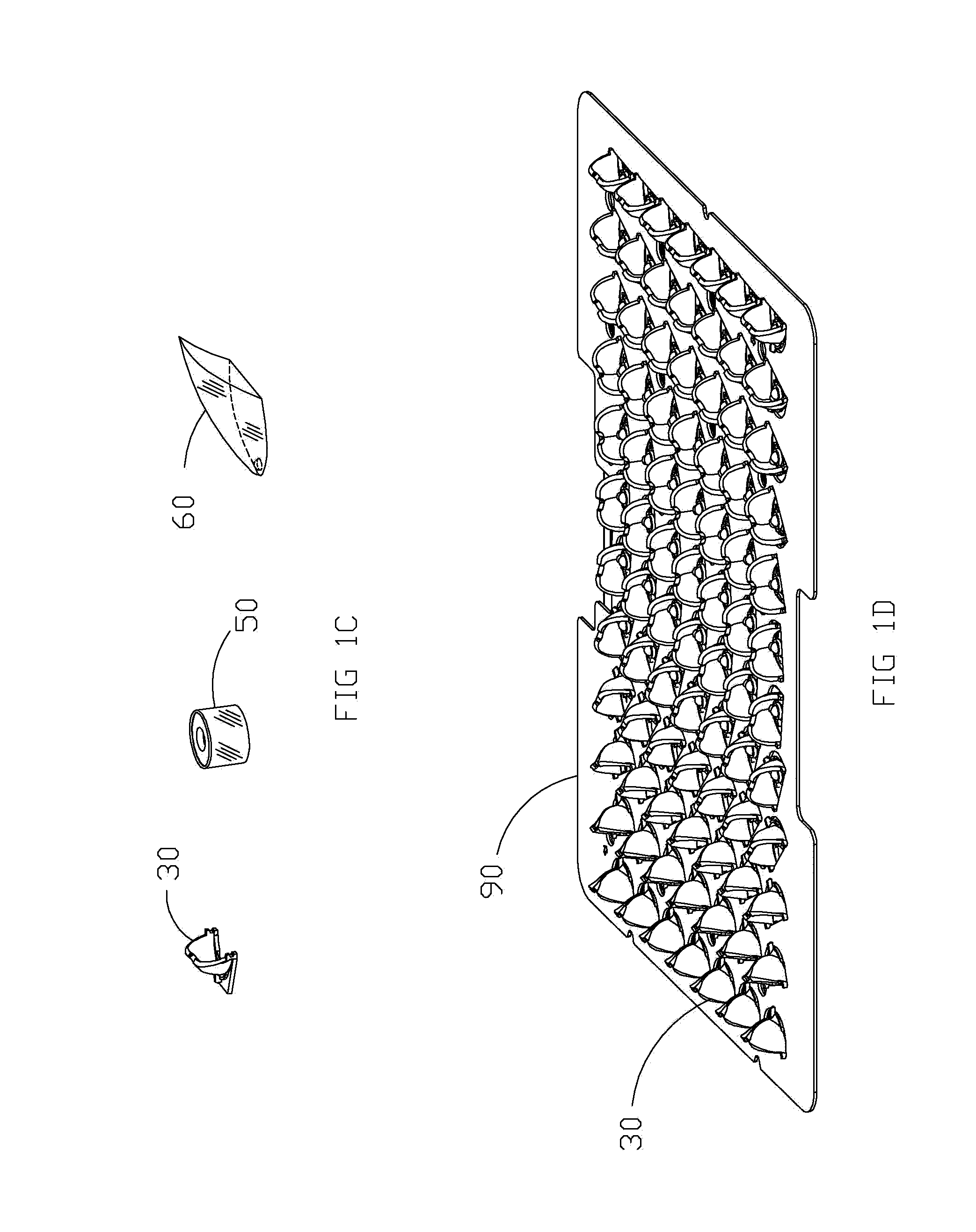
[0073]With respect to FIGS. 1A-E said fixture(s) contains a plurality, which may be a large plurality, of individual light sources 20 and their associated optics. Associated optics may include reflectors 30, refractive lenses 50, TIR lenses 60, or other lens types. The determination of which type of associated optics elements to use may be based on applicability to a particular use, which may include consi...


PUM

PropertyMeasurementUnit
areaaaaaaaaaaa
areaaaaaaaaaaa
angles of incidenceaaaaaaaaaa

Abstract

Disclosed herein are apparatus, methods, and systems for deriving composite beams from a plurality of light sources such as LEDs. Optical units comprising a plurality of light sources, each source having an associated optic which is individually positionable, are developed using optimization techniques that allow for lighting different target areas in an effective manner by rotating or otherwise positioning the reflectors, refractive lenses, TIR lenses, or other lens types to create a composite beam. The apparatus, methods, and systems of lighting herein make it possible to widely vary the types of beams from an available fixture using a small number of optics and fixtures. In some cases, by using a combination of individual beam patterns from the same or different types of light sources, a small set of individual optics may be sufficient to create a majority of the typical and specialized composite beams needed to meet the needs of most lighting projects and target areas.

Description

CROSS-REFERENCE TO RELATED APPLICATIONS[0001]This application is a continuation-in-part of PCT application No. PCT / US09 / 57090 filed Sep. 16, 2009 which claims priority to U.S. Ser. No. 61 / 097,483 filed Sep. 16, 2008, both of which are hereby incorporated by reference in their entireties.I. BACKGROUND OF THE INVENTION[0002]Embodiments of the present invention generally relate to systems and methods for lighting. In particular, embodiments of the present invention relate to systems, methods, and apparatus for highly controlled light distribution from a light fixture using multiple light sources, such as light emitting diodes (LEDs).[0003]Existing high intensity discharge (HID) fixtures use single large light sources which provide light beams which may be controlled somewhat by varying reflector design and mounting orientation. Typical LED fixtures having multiple small light sources function similarly. Each small light source has an optic (reflective or refractive lens) which creates ...

Claims


Application Information

Patent Timeline
Patent Type & Authority Applications(United States)
IPC IPC(8): H01L33/00F21V13/00F23Q23/08
CPCF21S2/005F21Y2115/10F21V5/04F21V7/0025F21V7/0083F21V7/0091F21V11/16F21V17/02F21V19/001F21W2131/103F21W2131/107F21V11/00F21V14/00G02B19/0066G02B19/0023G02B19/0028F21S8/086Y10T29/49002F21Y2105/12F21V5/007
Inventor GORDIN, MYRONBOXLER, LAWRENCE H.DROST, MATTHEW D.MCKEE, LUKE C.LICKISS, CHRIS P.
Owner MUSCO
Why Eureka
Try Eureka