This helps you quickly interpret patents by identifying the three key elements:
Problems solved by technology
Method used
Benefits of technology
Benefits of technology
[0020]According to the mobile communication terminal according to the present invention, with the first housing 1 and the second housing 2 closed, information at the time of communication can be indicated by the second display 21 of the second housing 2, and moreover, with the first housing 1 and the second housing 2 open, in the case where an image is displayed over the screens of the displays 11, 21, continuousness of the image can be maintained to prevent a feeling of strangeness regarding the image displayed over two displays.
Problems solved by technology
However, since the size of the screen of the display is limited by the size of the housing, the increase in the size of the display has a limitation.
Method used
Image
Click on the blue label to locate the original text in one second.
Reading with bidirectional positioning of images and text.
Examples
first embodiment
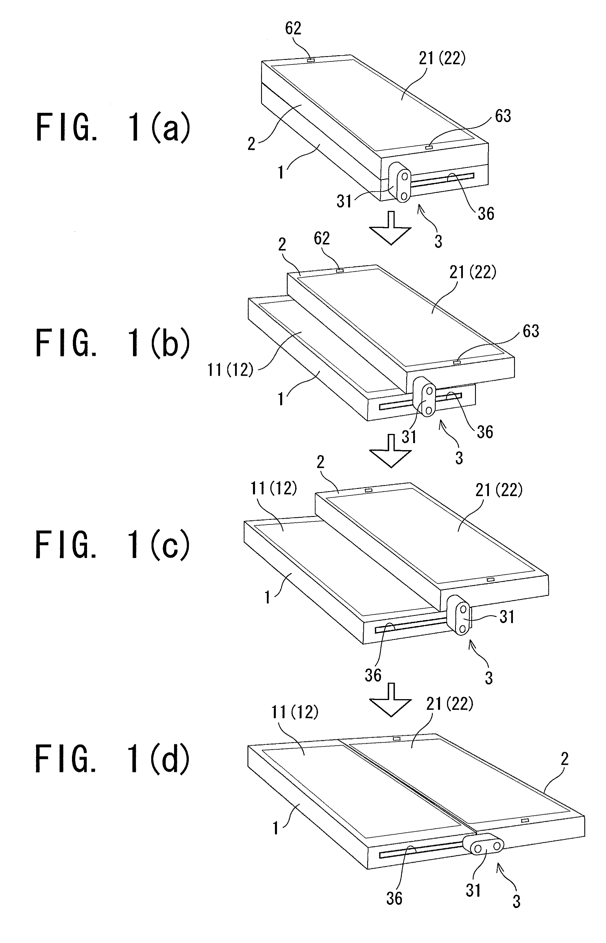
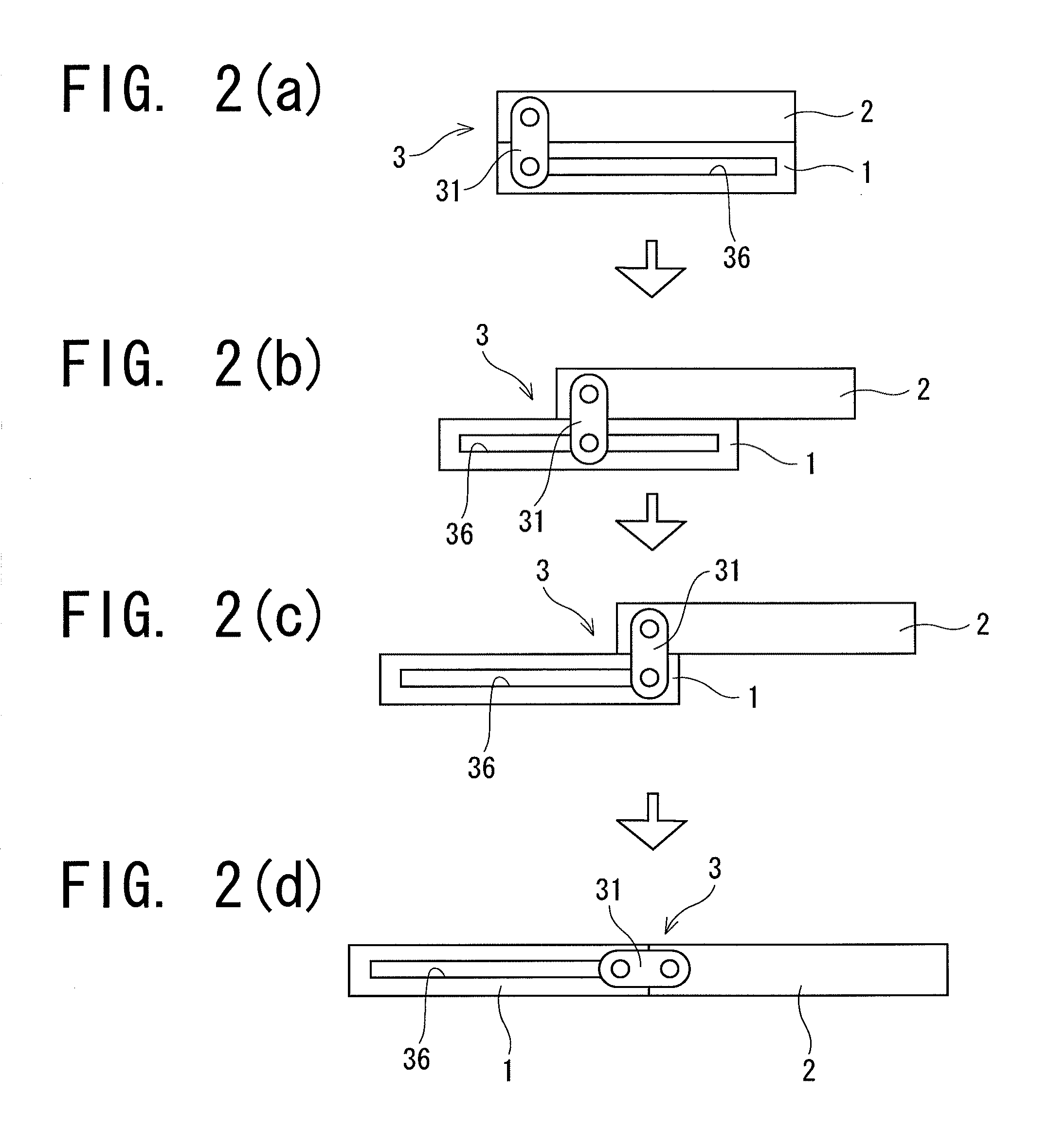
[0044]As shown in FIGS. 1(a) to 1(d), a portable telephone of a first embodiment comprises a first housing 1 and a second housing 2 each having a flat rectangular parallelepiped shape, which are connected so as to be movable relative to each other by a connecting mechanism 3.
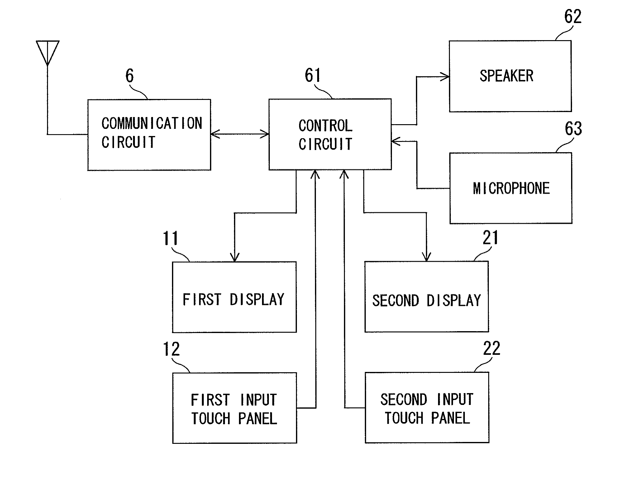
[0045]A first display 11 comprising a liquid-crystal display panel is placed on a front face of the first housing 1, and a transparent first input touch panel 12 is placed so as to cover an entire front face of the first display 11.
[0046]A second display 21 comprising a liquid-crystal display panel is placed on a front face of the second housing 2, and a transparent second input touch panel 22 is placed so as to cover an entire front face of the second display 21.
[0047]Also, on the front face of the second housing 2, a speaker 62 is provided to one end part, and a microphone 63 is provided to the other end part.
[0048]The connecting mechanism 3 is arranged on either side of the first housing 1 and the second hous...
second embodiment
[0061]As shown in FIGS. 5(a) to 5(d), a portable telephone of a second embodiment comprises a first housing 1 and a second housing 2 each having a flat rectangular parallelepiped shape, which are placed on a base 4 and connected so as to be movable relative to each other by a connecting mechanism 3.
[0062]A first display 11 comprising a liquid-crystal display panel is placed on a front face of the first housing 1, and a transparent first input touch panel 12 is placed so as to cover an entire front face of the first display 11.
[0063]A second display 21 comprising a liquid-crystal display panel is placed on a front face of the second housing 2, and a transparent second input touch panel 22 is placed so as to cover an entire front face of the second display 21.
[0064]Also, on the front face of the second housing 2, a speaker 62 is provided to one end part, and a microphone 63 is provided to the other end part.
[0065]The connecting mechanism 3 is arranged on either side of the first housi...
PUM
Abstract
A mobile communication terminal which can indicate information on a single display with a first housing and a second housing closed, and moreover, maintain continuousness of an image displayed over two display screens with the housings open.The portable communication terminal according to the present invention comprises the first housing 1 and the second housing 2 that are connected to each other. A first display 11 is placed on the front face of the first housing 1, a second display 21 is placed on the front face of the second housing 2, and a second input touch panel 22 is placed on the front face of the second display 21 to cover at least a part of this front face. The first housing 1 and the second housing 2 are relatively movable between a closed position and an open position. At the closed position, the rear face of the second housing 2 is superposed on the front face of the first housing 1. At the open position, the front face of the first display 11 and the front face of the second display 21 are aligned flush with each other and both the displays 11, 21 are set adjacent to each other.
Description
TECHNICAL FIELD[0001]The present invention relates to a mobile communication terminal such as a portable telephone or the like, and particularly to a dual screen mobile communication terminal comprising a first housing and a second housing each including a display arranged thereon.BACKGROUND ART[0002]In recent years, portable telephones have been multi-functionalized more and more, and along with this, information to be displayed on a display has become various. Therefore, the size of a screen of the display has been increased. However, since the size of the screen of the display is limited by the size of the housing, the increase in the size of the display has a limitation.[0003]It has been proposed that in a display apparatus for a mobile, two housings are foldably connected to each other, and each of the housings includes a display arranged on an inner face thereof so as to display more information with the two screens (e.g., Japan Patent Laid-Open 11-167354).[0004]Therefore, con...
Claims
Application Information
Patent Timeline
Application Date:The date an application was filed.
Publication Date:The date a patent or application was officially published.
First Publication Date:The earliest publication date of a patent with the same application number.
Issue Date:Publication date of the patent grant document.
PCT Entry Date:The Entry date of PCT National Phase.
Estimated Expiry Date:The statutory expiry date of a patent right according to the Patent Law, and it is the longest term of protection that the patent right can achieve without the termination of the patent right due to other reasons(Term extension factor has been taken into account ).
Invalid Date:Actual expiry date is based on effective date or publication date of legal transaction data of invalid patent.

