Seatbelt apparatus for vehicle

Inactive Publication Date: 2003-11-13
NISSAN MOTOR CO LTD
View PDF8 Cites 26 Cited by
  • Summary
  • Abstract
  • Description
  • Claims
  • Application Information

AI Technical Summary

Benefits of technology

0006] Under the above circumstance, it is an object of the present invention to provide a seatbelt apparatus that can afford a passenger

Problems solved by technology

In the conventional device to control the operation of the passenger's restraint, however, it is difficult to make a passen

Method used


Image

  • Seatbelt apparatus for vehicle
  • Seatbelt apparatus for vehicle
  • Seatbelt apparatus for vehicle

Examples


first embodiment

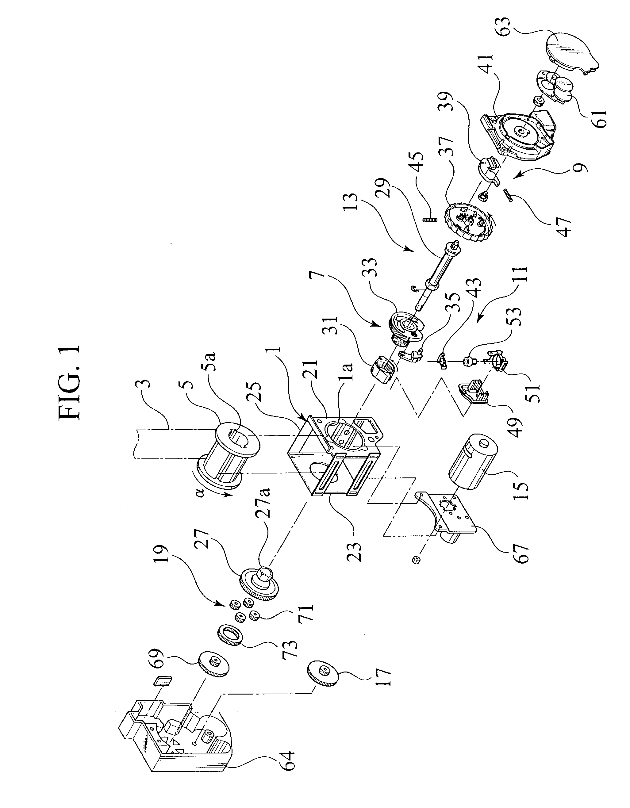
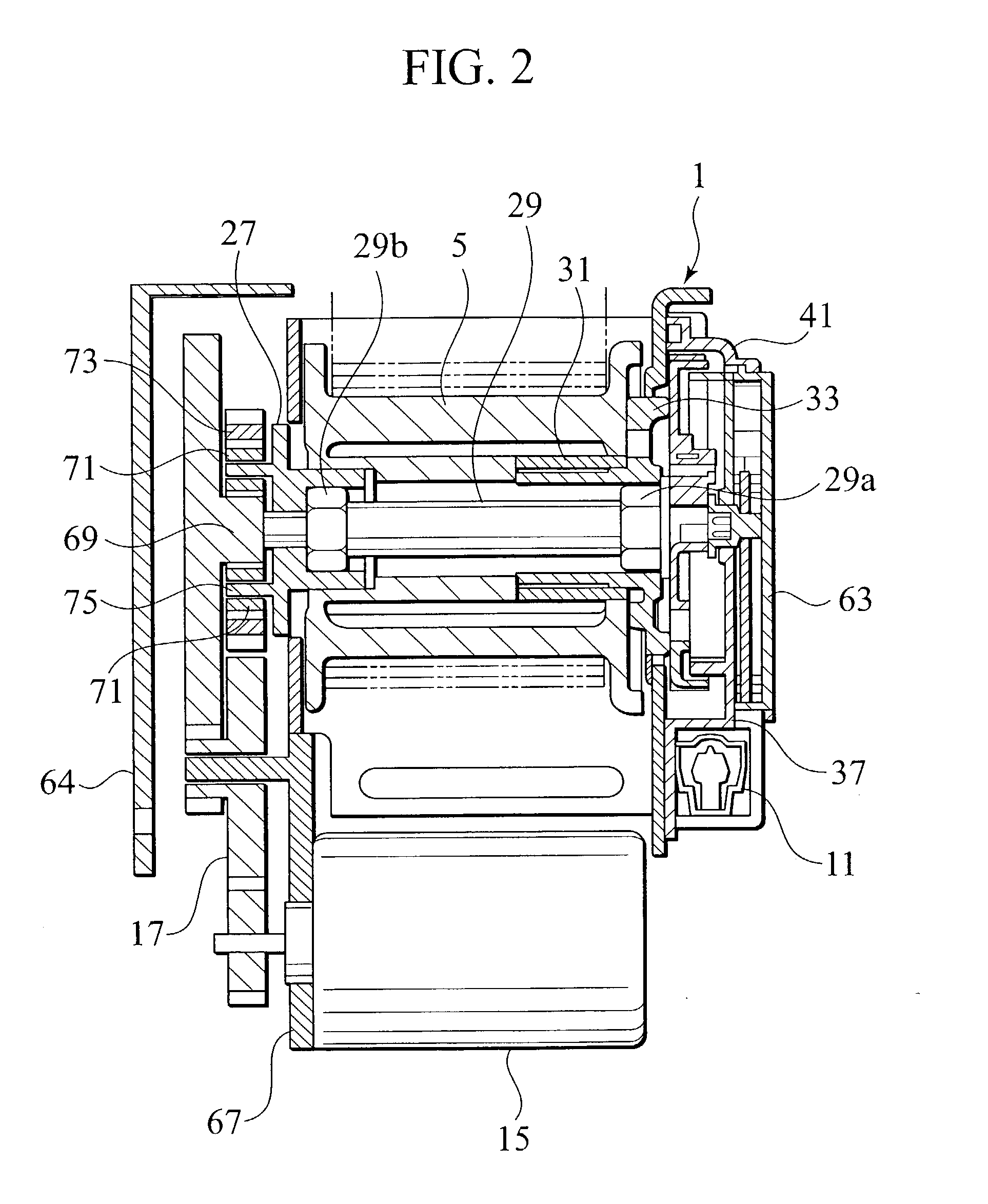
[0041] FIG. 1 is an exploded perspective view of a seatbelt apparatus for a vehicle, in accordance with the present invention. FIG. 2 is a longitudinal sectional view of the same apparatus in its assembled state. It is assumed here that the shown seatbelt apparatus is applied to each of a driver seat and an assistant driver's seat in one form of another seat except the driver seat.

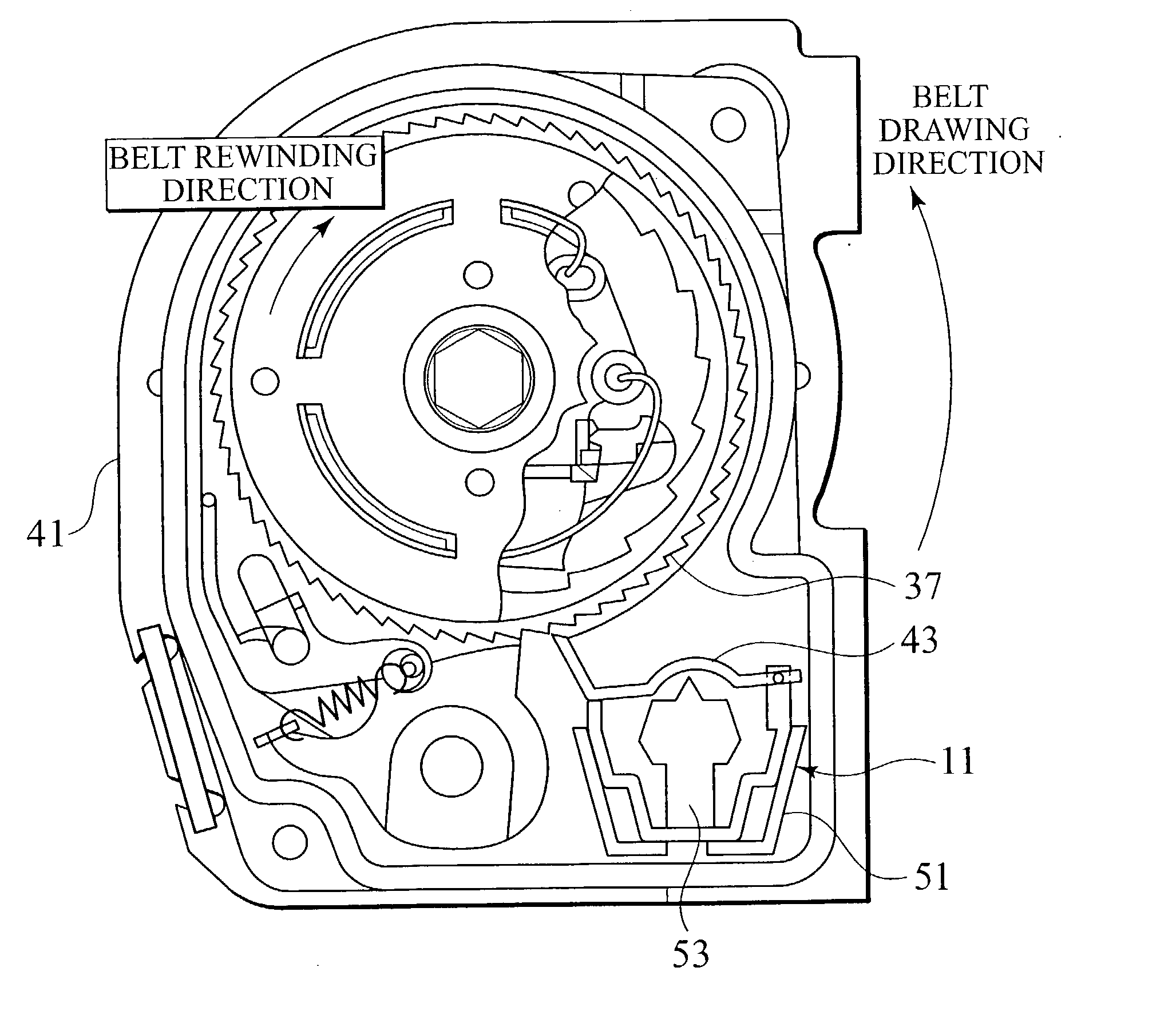
[0042] As shown in FIG. 1, the seatbelt apparatus generally includes a frame 1, a reel 5 for rewinding a seatbelt 3, a lock mechanism 7 arranged on one side of the frame 1 (front side of FIG. 1) to retard the rotation of the reel 5 in a direction .alpha. to draw the seatbelt 3 from the reel 5, a lock actuating mechanism 9 for actuating the lock mechanism 7 as occasion demands, an acceleration sensing mechanism 11, a force limiting (EA) mechanism 13, a motor 15 arranged on the other side of the frame 1 (back side of FIG. 1) to generate a belt rewinding torque, a reduction gear 17 for reducing a torque of th...

second embodiment

[0098] The operation of the second embodiment will be described with reference to FIGS. 17 to 19.

[0099] FIG. 17 shows an overall flow chart for carrying out a program of the second embodiment. First of all, when the ignition switch 103 is turned on, the program is started. At step 1701, it is executed to input the signals from the fore-and-aft acceleration (longitudinal acceleration) sensor 97 and the left-and-right acceleration (lateral acceleration) sensor 99. Next, at step 1703, it is executed to perform an assistant driver's seat control mentioned later. Continuously, at step 1705, it is executed to perform a driver seat control also mentioned later. At step 1707, it is executed to judge whether the ignition switch 103 is turned off or not. If the judgment at step 1707 is Yes (i.e. turn-off), then the routine of the program is ended. While, if the judgment at step 1707 is No (i.e. turn-on), then the routine returns step 1701 to input the signals from the sensors 97, 99.

[0100] FI...

third embodiment

[0117] FIG. 22 shows an overall flow chart for carrying out the above control program of the First of all, when the ignition switch 103 is turned on, the program is started. At step 2201, it is executed to input the signal from the fore-and-aft acceleration (longitudinal acceleration) sensor 97. Next, at step 2203, it is executed to calculate a rising value of the fore-and-aft acceleration (i.e. rise of longitudinal acceleration: .DELTA.longitudinal acceleration). Continuously, at step 2205, it is judged whether the seatbelt control system for the assistant driver's seat is not under control now.

[0118] If the judgment at step 2205 is Yes (not under control), then the routine goes to step 2207 to carry out the operation to rewind the seatbelt in accordance with a flow chart of FIG. 23.

[0119] In the flow chart of FIG. 23, at step 2301, it is executed to compare a value of the longitudinal acceleration with a threshold value Gx3. When the longitudinal acceleration is smaller than the ...


PUM


Abstract

A seatbelt apparatus is provided to apply a proper restrictive feeling on passengers, corresponding to traveling condition of a vehicle. In the seatbelt apparatus, on receipt of detection signals from a fore-and-aft acceleration sensor 97 and a left-and-right acceleration sensor 99, a controller 101 controls respective tensions of seatbelts for driver seat and assistant driver's seat individually. Owing to the controller 101, it is established at a vehicle's breaking to make a seatbelt tension of the assistant driver's seat larger than that of the driver seat. When the vehicle is turning, it is carried out to make a seatbelt tension of the driver seat larger than that of the assistant driver's seat.

Description

BACKGROUND OF THE INVENTION[0001] 1. Field of the Invention[0002] The present invention relates to a seatbelt apparatus for a vehicle, such as an automobile.[0003] 2. Description of Related Art[0004] Japanese Patent Application Laid-open No. 11-20606 and 2000-318567 each disclose a control device for controlling the operation of automotive restraints (e.g. seatbelt, air bag) for restraining the movements of passengers in a vehicle cabin. In the above publications, the control device is constructed so as to control the action of seatbelts for passengers' seats (driver seat, assistant driver's seat, etc.) or the operation of air bags. In the control device, the operation of a restraint (e.g. seatbelt, air bag) is modified corresponding to a situation whether a passenger related to the restraint has recognized a vehicle collision in advance of the operation of the restraint. Or again, depending on the operation of one of restraints for the driver seat and the assistant driver's seat, t...

Claims


Application Information

Patent Timeline
IPC IPC(8): B60R21/01B60R22/48B60R21/0132B60R21/015B60R22/44B60R22/46
CPCB60R21/0132B60R21/015B60R22/44B60R21/0155B60R2022/4666B60R21/01548B60R2022/4473
Inventor TOBATA, HIDEO
Owner NISSAN MOTOR CO LTD
Why Eureka
Try Eureka